Head-cooling pillow and head-cooling device

A cooling device and technology for the head, applied in the field of head cooling pillows, can solve the problems of feeling uncomfortable and unpleasant for the user, and achieve the effect of improving the feeling

Inactive Publication Date: 2013-02-06
LIGHT OPTICAL WORKS
View PDF8 Cites 4 Cited by
  • Summary
  • Abstract
  • Description
  • Claims
  • Application Information

AI Technical Summary

Problems solved by technology

However, in this continuous water cooler, since the head is supported by the thin plate-shaped partition plate, the feeling of resting the head on the pillow is uncomfortable, which brings discomfort to the user.

Method used


Image

  • Head-cooling pillow and head-cooling device
  • Head-cooling pillow and head-cooling device
  • Head-cooling pillow and head-cooling device

Examples


Embodiment Construction

[0056] Hereinafter, embodiments of the present invention will be described with reference to the drawings.

[0057] (Schematic structure of the head cooling device)

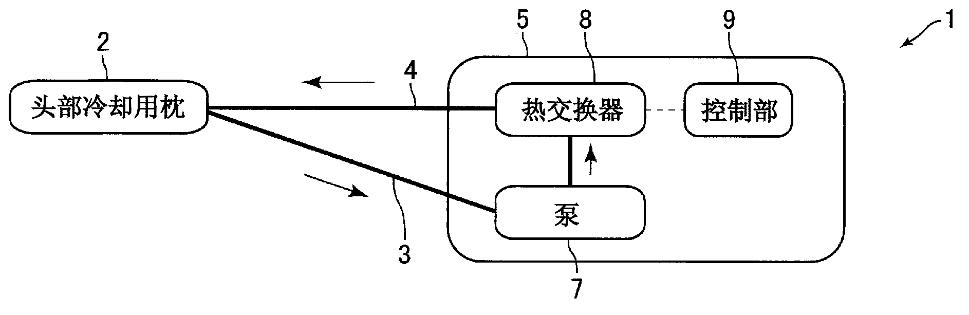
[0058] figure 1 It is a block diagram showing a schematic configuration of the head cooling device 1 according to the embodiment of the present invention.

[0059] The head cooling device 1 of the present embodiment is a device for cooling the head of a user who is lying down, and is installed and used on a bed in a hospital or a nursing institution, for example. Such as figure 1 As shown, the head cooling device 1 includes: a head cooling pillow 2 (hereinafter referred to as "pillow 2") on which a user's head is placed, and a mechanism connected to the pillow 2 via flexible tubes 3 and 4. Part 5. A refrigerant such as water circulates between the pillow 2 and the mechanical part 5 . In addition, the pillow 2 is installed, for example, on a hospital bed, and the mechanical unit 5 is installed on a fence surr...


PUM


Abstract

A head-cooling pillow provided by the present invention is capable of increasing head-cooling efficiency and controlling pressure increase inside the pillow while also making the pillow more comfortable when a person's head is placed thereon. The head-cooling pillow (2) is provided with a main pillow body (11) that is formed in the shape of a sac through which a coolant is passed, a partitioning part (12b) disposed inside the main pillow body (11) to form a channel (13) through which the coolant passes, and support parts (12c) for supporting the user's head. In the head-cooling pillow (2), the head is cooled by the coolant that passes through the channel (13).

Description

technical field [0001] The present invention relates to a head cooling pillow for cooling a user's head, and a head cooling device including the head cooling pillow. Background technique [0002] An affected part cooling device for cooling a patient's head has been proposed (for example, refer to Patent Document 1). The affected part cooling device described in Patent Document 1 includes a pillow-shaped affected part cooling body (pillow) and a cooling device for cooling the pillow. The pillow includes a bag-shaped main body made of rubber or the like, and liquid silicone resin filled in the main body. Inside the pillow, a refrigerant tube is disposed so as to pass through the inside of the liquid silicone resin. In addition, the cooling device includes a heat exchanger for cooling the refrigerant passing through the refrigerant pipe, and a pump for feeding the refrigerant into the refrigerant pipe. In this affected part cooling device, the liquid silicone resin is cooled...

Claims


Application Information

Patent Timeline
Patent Type & Authority Applications(China)
IPC IPC(8): A61F7/10A47G9/10
CPCA61F2007/0056A61F7/0053A61F7/0085A47G9/1036A61F2007/0274A61F2007/0002A61F2007/0076A47G9/10A61F7/10
Inventor 岩波雅富浦井克二
Owner LIGHT OPTICAL WORKS
Why Eureka
Try Eureka