Sign comprising a film-based lightguide

A technology of light guides and waveguides, applied in the directions of light guides, light guide light guides, illuminated markers, etc.

Inactive Publication Date: 2013-02-06
FLEX LIGHTING II
View PDF92 Cites 15 Cited by
  • Summary
  • Abstract
  • Description
  • Claims
  • Application Information

AI Technical Summary

Problems solved by technology

When fabricated, thin lightguides are limited by the rigid wafer of the monolithic optical assembly

Method used


Image

  • Sign comprising a film-based lightguide
  • Sign comprising a film-based lightguide
  • Sign comprising a film-based lightguide

Examples


Embodiment

[0958] Certain embodiments are illustrated in the following examples. The following examples are given for illustrative purposes only, and do not limit the scope or spirit of the invention.

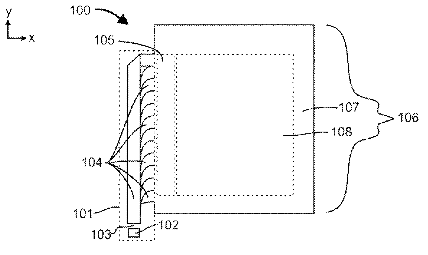
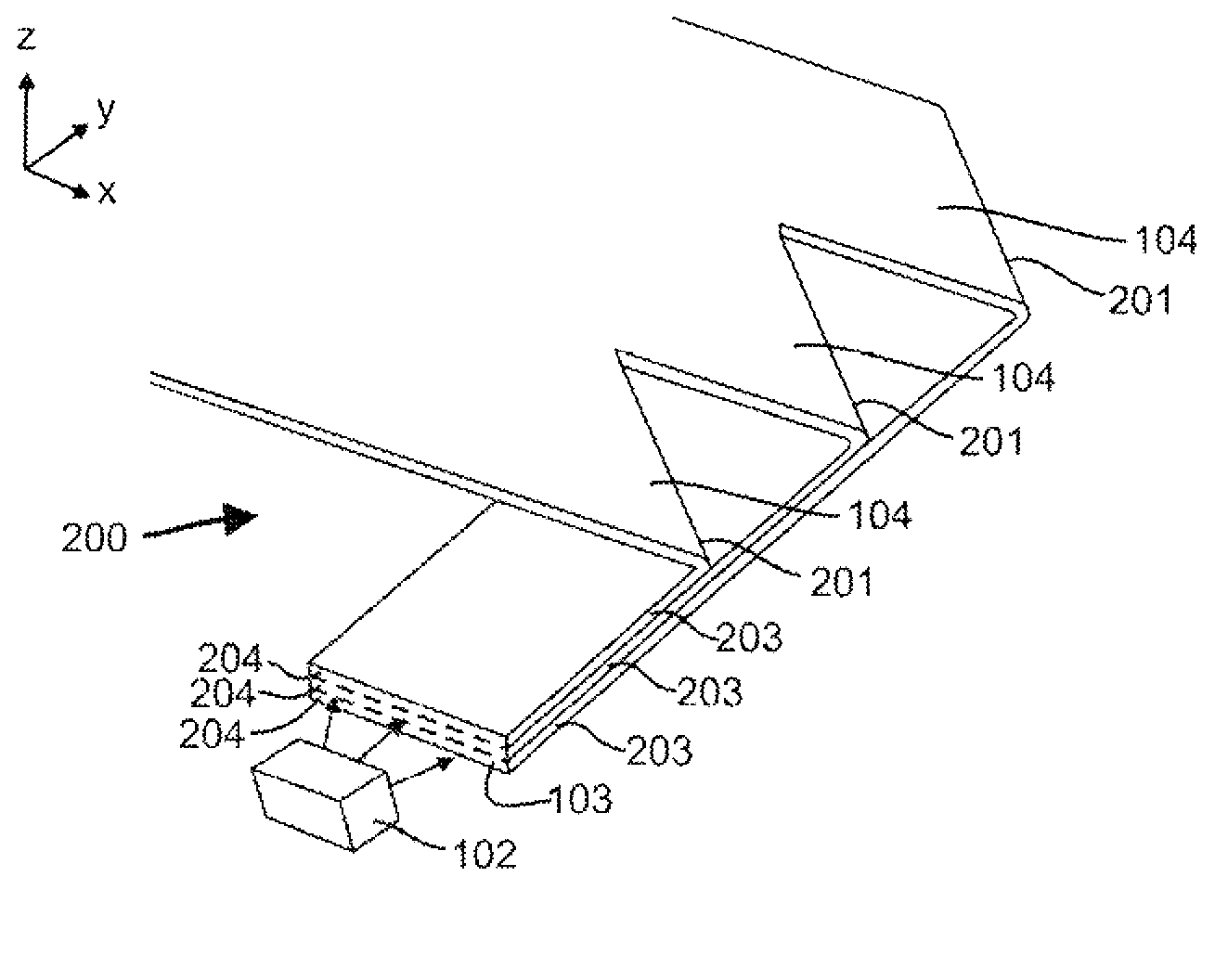
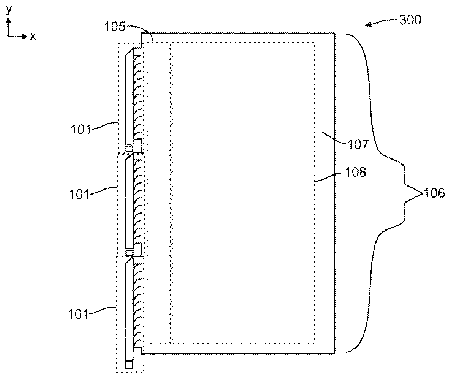
[0959] In one embodiment, the coupling lightguides are formed by cutting strips at one or more ends of the film forming the coupling lightguides (strips) and the lightguide region (remainder of the film). On the free end of the strip, the strip is bundled together into an arrangement, the strip being thicker than the thickness of its membrane. On the other end, they are still physically and optically attached and aligned to the larger film lightguide. Film cuts are obtained by stamping, laser cutting, mechanical cutting, water jet cutting, local melting or other film processing methods. Preferably, the cutting results in an optically smooth surface to facilitate total internal reflection of light, thereby improving guiding light through the length of the strip. A light source is couple...


PUM

PropertyMeasurementUnit
thicknessaaaaaaaaaa
sizeaaaaaaaaaa
sizeaaaaaaaaaa

Abstract

A device includes a light transmitting film defining a lightguide region. A first region is defined within the lightguide region representing a region of one or more of an indicia, a graphic, and an image that is visible by light extraction when illuminated by light propagating within the film in a waveguide condition, wherein the first region includes a plurality of light extraction features that redirect a portion of light traveling within the film in a waveguide condition out of a first face of the opposing faces of the film in the first region, and the first region has a luminance less than 50 cd / m2 when illuminated with 1000 lux of diffuse light when disposed on an opening of a light trap box comprising a plurality of walls and a black, light absorbing material lining the plurality of walls. A method of making or producing a device is also disclosed.

Description

[0001] Cross References to Related Applications [0002] This application requests U.S. Provisional Application No. 61 / 325,266, filed April 16, 2010, entitled "Replaceable illuminated signage system for cooler doors"; filed April 16, 2010, entitled "Manufacturing device for ultra-low profile U.S. Provisional Application No. 61 / 325,252 for "film lightguide"; U.S. Provisional Application No. 61 / 325,269 entitled "Processing method for optical film lightguide and coupling system," filed April 16, 2010; April 16, 2010 U.S. Provisional Application No. 61 / 325,271, filed April 16, 2010, titled "Method and apparatus for aligning lightguides in a coupling system" and titled "Center aligned lighting configuration for ultra-thin LED backlight system for LCDs" U.S. Provisional Application No. 61 / 325,272, filed April 16, 2010, entitled "Low profile battery powered lightguide"; filed April 16, 2010, entitled "Method and Apparatus for enhanced LCD backlight" U.S. Provisional Application No. 61...

Claims


Application Information

Patent Timeline
Patent Type & Authority Applications(China)
IPC IPC(8): G02B6/10F21Y101/00
CPCG02B6/0088G02B6/0068G02F2001/133616G02B6/006G02B6/0065G02B6/002G09F13/18G02B6/0018G02B6/005Y02B20/42G02B6/003G02B6/0028G02B6/0076G02B27/0101Y10T29/49826G02F1/133616G02B6/0053
Inventor A·J·尼科尔Z·科尔曼
Owner FLEX LIGHTING II
Why Eureka
Try Eureka