Motor control apparatus
A control device and motor technology, which is applied in motor control, non-electric variable control, mechanical oscillation control, etc., can solve the problems of large phase delay, inability to fully improve the gain of the control system, and inability to fully suppress oscillation, etc. The effect of resonance
- Summary
- Abstract
- Description
- Claims
- Application Information
AI Technical Summary
Problems solved by technology
Method used
Image
Examples
Embodiment approach 1
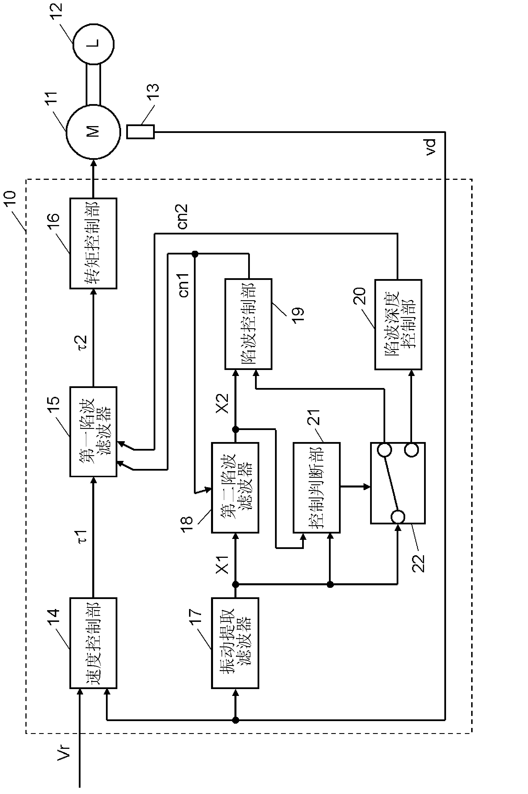
[0033] figure 1 It is a block diagram showing the configuration of the motor control device 10 according to Embodiment 1 of the present invention.
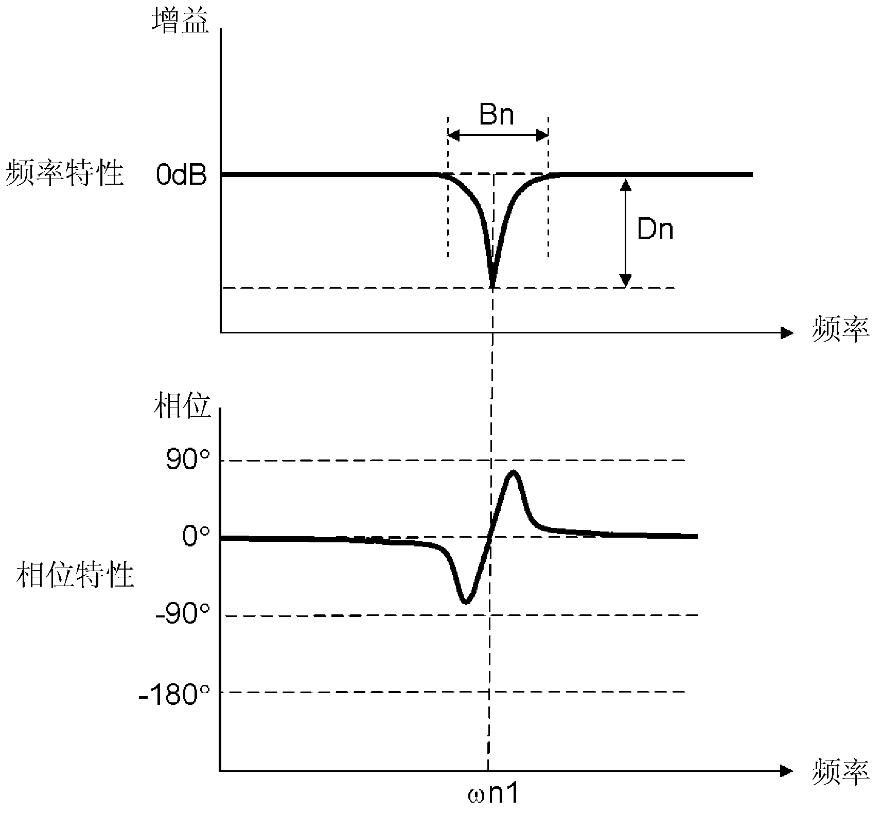
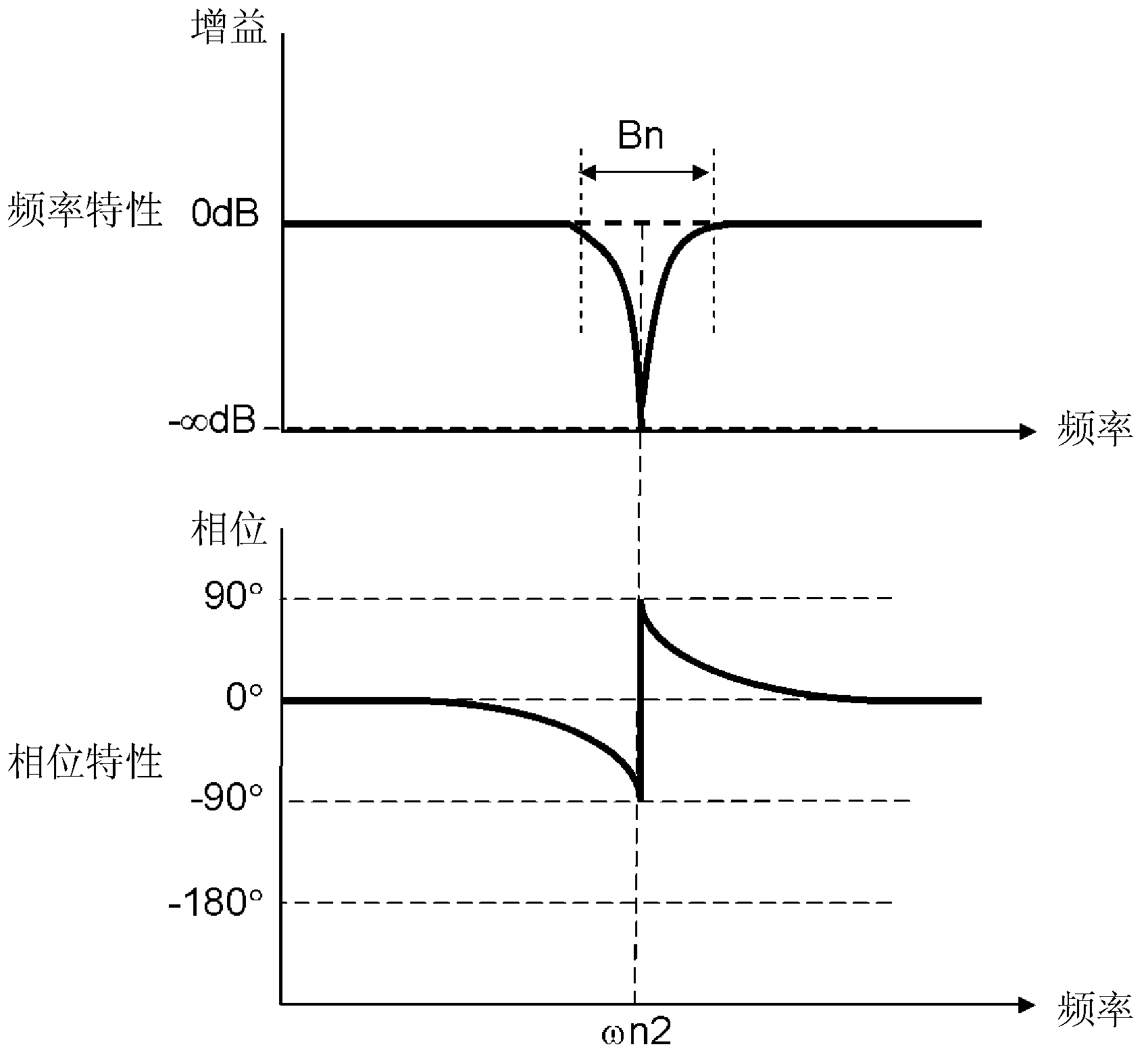
[0034] Such as figure 1 As shown, the motor control device 10 according to Embodiment 1 of the present invention is connected to a motor 11 and a speed detector 13 . A load 12 is connected to the motor 11 . Also, the speed detector 13 measures the rotational speed of a movable element (not shown) arranged in the motor 11, and outputs a state detection signal indicating a speed amount corresponding to the rotational speed, that is, a speed detection signal Vd. On the other hand, an instruction speed signal Vr is notified to the motor control device 10 in order to instruct the rotation speed of the movable element. The motor control device 10 includes, as a control system that performs feedback control, a speed control system that performs feedback control such that the rotational operation of the movable element follows a comm...
Embodiment approach 2
[0067] In Embodiment 1, a configuration example in which the set value cn2 is gradually decreased has been described. On the other hand, in Embodiment 2, it is set as the structure which further includes the process which makes setting value cn2 gradually larger. That is, the motor control device 10 according to the present embodiment is, for example, configured to select one of the changing operation of gradually increasing the set value cn2 and the changing operation of gradually decreasing the set value cn2 in accordance with the change of the control system gain. One.
[0068] Here, first, frequency characteristics of a control system including mechanical resonance and the like will be described. Image 6 It is a graph showing the gain characteristic of the transfer function of the speed detection signal Vd with respect to the command speed signal Vr. exist Image 6 In , an example is shown in which the frequency ωn is the resonance frequency and the mechanical resonanc...
Embodiment approach 3
[0074] Figure 9 It is a flowchart showing the characteristic setting processing of the first notch filter 15 according to Embodiment 3 of the present invention. In this embodiment, for example, the following structure is set: Figure 7 In the case of increasing the control system gain in this way, the change amount of the set value cn2 is calculated by calculation.
[0075] which is, Figure 9 The shown processing has a structure in which the change amount of the set value cn2 is calculated and set in accordance with the change amount of the control system gain in the second and subsequent change operations of the set value cn2 . That is, when the control system gain is amplified by Kv, the set value cn2 is calculated so that the notch depth Dn is deeper than the current value by Kv.
[0076] use Figure 9 The flow charts illustrate specific actions. When the control judging section 21 judges in step S101 that there is no vibration component, it confirms in step S131 whe...
PUM
 Abstract
Description
Claims
Application Information
 - R&D
- Intellectual Property
- Life Sciences
- Materials
- Tech Scout
- Unparalleled Data Quality
- Higher Quality Content
- 60% Fewer Hallucinations
Browse by: Latest US Patents, China's latest patents, Technical Efficacy Thesaurus, Application Domain, Technology Topic, Popular Technical Reports.
© 2025 PatSnap. All rights reserved.Legal|Privacy policy|Modern Slavery Act Transparency Statement|Sitemap|About US| Contact US: help@patsnap.com


