
Vehicle drive control system

A vehicle and driving force technology, which is applied in the field of vehicle drive control devices, can solve problems such as inappropriate filter coefficients, natural frequency deviations of the drive system, and inability to drive system mechanical resonance attenuation, and achieve the effect of suppressing mechanical resonance and preventing deviations

Active Publication Date: 2015-06-10
HONDA MOTOR CO LTD
View PDF8 Cites 0 Cited by
  • Summary
  • Abstract
  • Description
  • Claims
  • Application Information

AI Technical Summary

Problems solved by technology

[0005] However, according to the speed control device of the above-mentioned conventional technology, the rotation speed of the motor may vary greatly depending on the behavior of the vehicle, and if the calculation of the filter coefficient based on the speed detection value is always performed, an inappropriate filter coefficient may be set.
[0006] For example, when a brake operation or an accelerator operation is performed that is close to the natural frequency of the drive system, if the filter coefficient is set to cut off the frequency components of these operations, there will be such a problem that the drive system The natural frequency deviates and cannot attenuate the mechanical resonance of the drive system

Method used


Image

  • Vehicle drive control system
  • Vehicle drive control system
  • Vehicle drive control system

Examples


Embodiment Construction

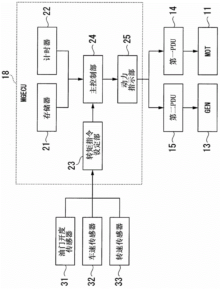
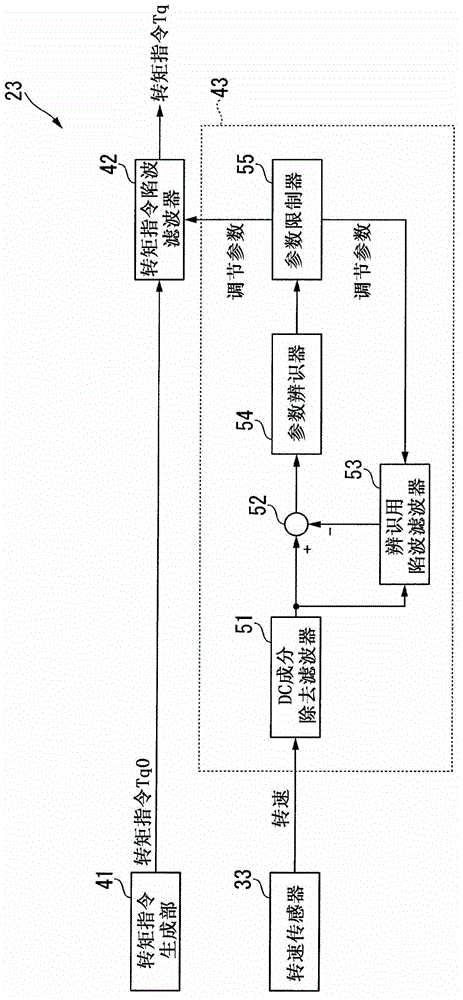
[0035] Next, a vehicle drive control device according to an embodiment of the present invention will be described with reference to the drawings.

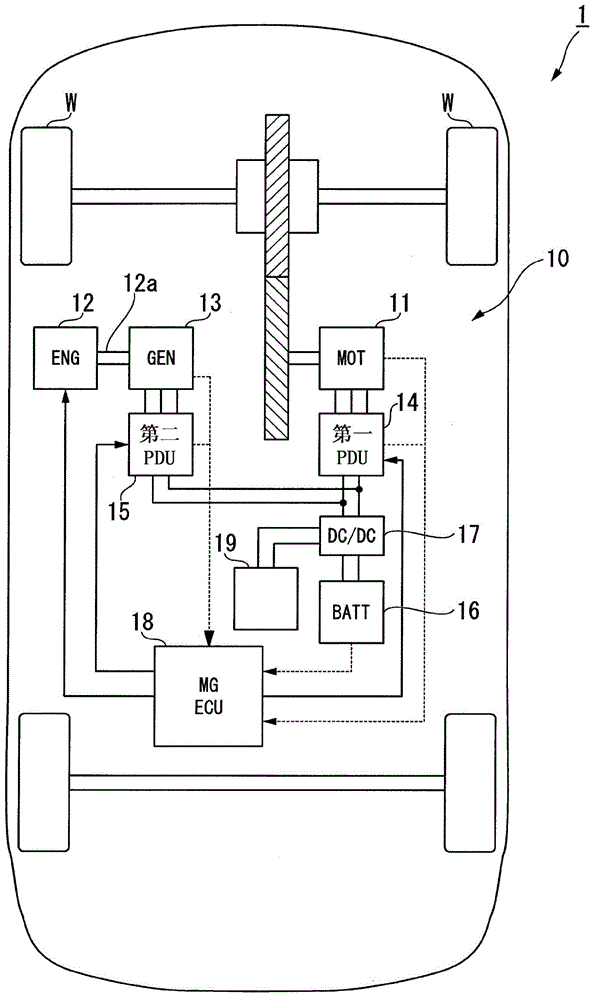
[0036] The drive control device 10 for a vehicle according to the present embodiment is mounted on, for example, figure 1 In the shown hybrid vehicle 1 , the hybrid vehicle 1 is, for example, a series type hybrid vehicle in which a running motor (MOT) 11 is connected to drive wheels W, and a power generation motor (GEN) 13 is connected to an internal combustion engine (ENG) The crankshaft 12a of 12 is connected.

[0037] Each motor 11 , 13 is, for example, a three-phase DC brushless motor or the like, and is connected to each power transmission unit (PDU) 14 , 15 that controls each motor 11 , 13 .

[0038] Each of the PDUs 14 and 15 is configured to include, for example, a PWM inverter based on pulse width modulation (PWM) including a bridge circuit formed by bridge-connecting switching elements such as a plurality of transistors. ...


PUM


Abstract

A vehicle drive control system includes a motor, a rotational speed detector, an accelerator opening degree detector, a vehicle speed detector, a torque instruction outputting device, an attenuation filtering device, and a controller. The attenuation filtering device is configured to perform attenuation filtering to a torque instruction to attenuate a natural oscillation frequency component of a torque transmission system of a vehicle and configured to output a filtered torque instruction after the attenuation filtering. The attenuation filtering device is configured to identify an attenuation characteristic of the attenuation filtering if the rotational speed of the motor is smaller than or equal to a predetermined rotational speed and the torque of the motor is higher than or equal to a predetermined torque. The controller is configured to cause the motor to generate a torque corresponding to the filtered torque instruction.

Description

technical field [0001] The invention relates to a driving control device for a vehicle. Background technique [0002] Conventionally, for example, there is known a speed control device as follows: In order to automate the adjustment of the filter for suppressing the mechanical resonance generated when the load is driven, the output side of the speed detector is provided with a filter that can limit the filter coefficient corresponding to the adjustable frequency. A filter for passing frequency components, the speed control device is provided with a filter coefficient setting unit that calculates a filter coefficient that is used to limit and output by the speed detector and outputs the calculation result to the filter. Passage of the frequency components superimposed on the speed detection value (for example, refer to Patent Document 1). [0003] prior art literature [0004] Patent Document 1: Japanese Patent Application Laid-Open No. 4-91689 [0005] However, according ...

Claims


Application Information

Patent Timeline
Patent Type & Authority Patents(China)
IPC IPC(8): B60K26/02B60L50/15
CPCB60K6/46B60W10/08B60W20/00B60W30/20B60W2510/081B60W2540/10B60W2710/083Y02T10/62Y02T10/72B60L15/20
Inventor 玉川裕
Owner HONDA MOTOR CO LTD
Learn More