Clamping mechanism for welding machines

A clamping mechanism and welding machine technology, applied in welding equipment, auxiliary welding equipment, welding/cutting auxiliary equipment, etc., can solve problems affecting the positioning accuracy of sliding guide rails, shorten the service life of clamping mechanisms, etc., and achieve simple structure and extended The effect of service life

Active Publication Date: 2013-02-13
DONGGUAN CITY JUNZHI AUTOMATION MACHINERY
View PDF6 Cites 0 Cited by
  • Summary
  • Abstract
  • Description
  • Claims
  • Application Information

AI Technical Summary

Problems solved by technology

The existing tool head clamping mechanism needs to use the sliding guide rail to control the locking and loosening operation of the chuck. Under the condition of long-term use, the long-term wear and tear between the chuck and the sliding guide rail greatly affects the positioning accuracy of the sliding guide rail, thus Reduced service life of the clamping mechanism

Method used


Image

  • Clamping mechanism for welding machines
  • Clamping mechanism for welding machines
  • Clamping mechanism for welding machines

Examples


Embodiment 1

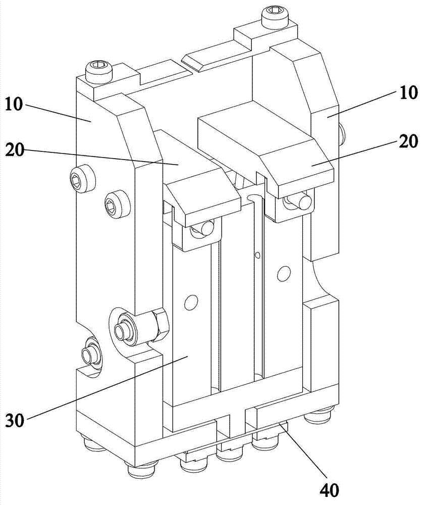
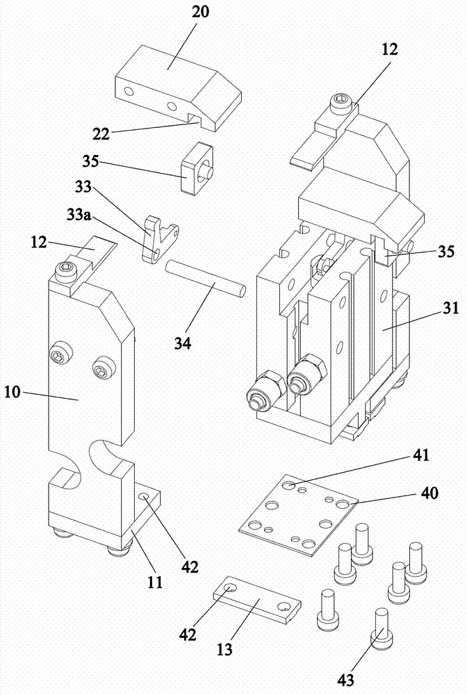
[0028] refer to Figure 1 to Figure 5 , a welding machine clamping mechanism, suitable for the clamping operation when welding the alloy cutter head on the saw blade welding machine, including a pair of symmetrically arranged cutter head clamps 10, the upper ends of the cutter head clamps 10 are respectively fixed and connected by screws There is a clamping block 20, so the clamping blocks 20 connected with the two cutter head tongs 10 are also symmetrically distributed, and the two clamping blocks 20 are respectively connected with the pneumatic fingers 30 to control the phase distance between the two clamping blocks 20. The lower ends of the two cutter head clamps 10 are respectively connected to the same flexible elastic piece 40, so that the hinge of the two cutter head clamps 10 can be realized by means of the flexibility of the elastic sheet 40, and the two clamps can be controlled by means of the pneumatic fingers 30. The distance between the blocks 20 is used to contro...

Embodiment 2

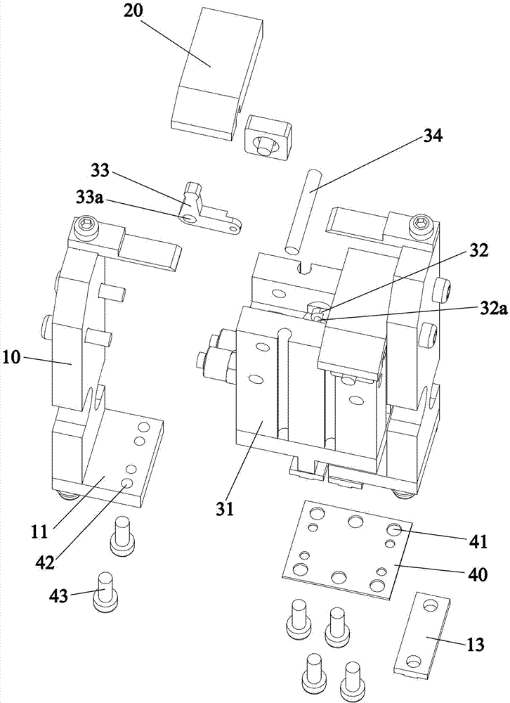
[0034] refer to Figure 6 to Figure 9 , the clamping mechanism of the welding machine in this embodiment is suitable for the clamping of the cutter head in the cutter head transmission mechanism, including two symmetrically arranged cutter head clamps 10, and the two cutter head clamps 10 are respectively connected to a pneumatic finger 30, specifically Specifically, the pneumatic finger 30 includes a body 31 and a piston rod 32, and a piston rod pin 32a is arranged at the top end 32 of the piston rod, and also includes two pins on both sides of the piston rod pin 32a that are connected through the piston rod pin 32a. Two rocker arms 33 are pivotally connected to the main body 31 through rocker arm positioning pins 34 . A fixing groove 14 is formed on the upper end of the cutter head clamp 10 at a position corresponding to the end of the rocker arm 33 , and the end of the rocker arm 33 is fitted into the fixing groove 14 . Preferably, the rocker arm 33 is an L-shaped rocker a...


PUM


Abstract

The invention discloses a clamping mechanism for welding machines, which is suitable for clamping a tool bit on a saw blade welding machine. The clamping mechanism comprises a pair of symmetrically-arranged tool bit clamps, the upper ends of the tool bit clamps are respectively connected with a pneumatic finger for controlling an opening between the tool bit clamps, and the lower ends of the tool bit clamps are respectively connected to a same elastic piece with flexibility. The clamping mechanism for welding machines, disclosed by the invention, replaces the traditional control mode of carrying out opening and closing operations on tool bit clamps by use of a sliding guide rail, so that the defects of poor positioning accuracy and short service life due to abrasion caused by that the tool bit clamps carry out reciprocating linear motion with the sliding guide rail for a long time are overcome. According to the invention, through fixedly connecting the two tool bit clamps to the same elastic piece with flexibility, the hinging of the two tool bit clamps is realized, so that the two tool bit clamps are controlled to be opened and closed repeatedly under the driving of the pneumatic finger; and the clamping mechanism is not only simple in structure, but also can realize approximately lossless hinging by aid of the flexibility of the elastic piece, thereby greatly prolonging the service life of the clamping mechanism.

Description

technical field [0001] The invention relates to a welding positioning and clamping device, in particular to a cutter head positioning and clamping device for welding processing of alloy saw blades. Background technique [0002] In order to save the cost of raw materials, most of the existing cutting and grinding processing tools, such as hard metal saw blades such as diamond cutting saw blades, mostly use high-hardness alloy blades welded on the base material saw blades for cutting. form. Since the welding surface of thin-walled substrates such as diamond saw blades is narrow, its welding strength mainly depends on the accuracy of the butt positioning of the welding substrates and the appropriateness of the welding temperature and welding time. [0003] Existing saw blade welding machines for thin-walled substrates usually include three parts: a welding mechanism, a substrate clamping and positioning mechanism, and a cutter head clamping and positioning mechanism. Among th...

Claims


Application Information

Patent Timeline
Patent Type & Authority Applications(China)
IPC IPC(8): B23K37/04
Inventor 孔海文
Owner DONGGUAN CITY JUNZHI AUTOMATION MACHINERY
Why Eureka
Try Eureka