Volute iron printing side mark device

A side gauge and volute technology, applied in printing, printing machines, rotary printing machines, etc., can solve the problems of low raw material utilization rate and increased labor cost, and achieve the effect of improving raw material utilization rate, reducing labor cost, and stable performance

Active Publication Date: 2013-02-13
SHANDONG HUANQIU TINPLATE CAN MAKING
View PDF5 Cites 2 Cited by
  • Summary
  • Abstract
  • Description
  • Claims
  • Application Information

AI Technical Summary

Problems solved by technology

[0003] The purpose of the present invention is to provide a scroll iron printing side gauge device for iron printing machines, so as to overcome the problem that the printing side gauges in the pr

Method used


Image

  • Volute iron printing side mark device
  • Volute iron printing side mark device
  • Volute iron printing side mark device

Examples


Example Embodiment

[0016] The present invention will be further described below in conjunction with the drawings.

[0017] In the picture:

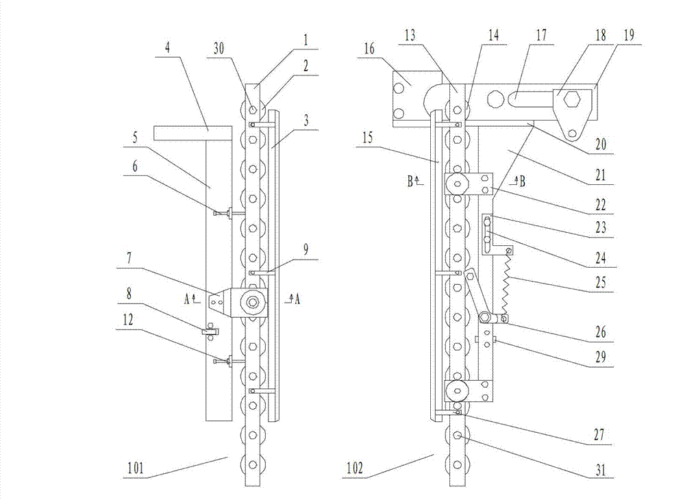
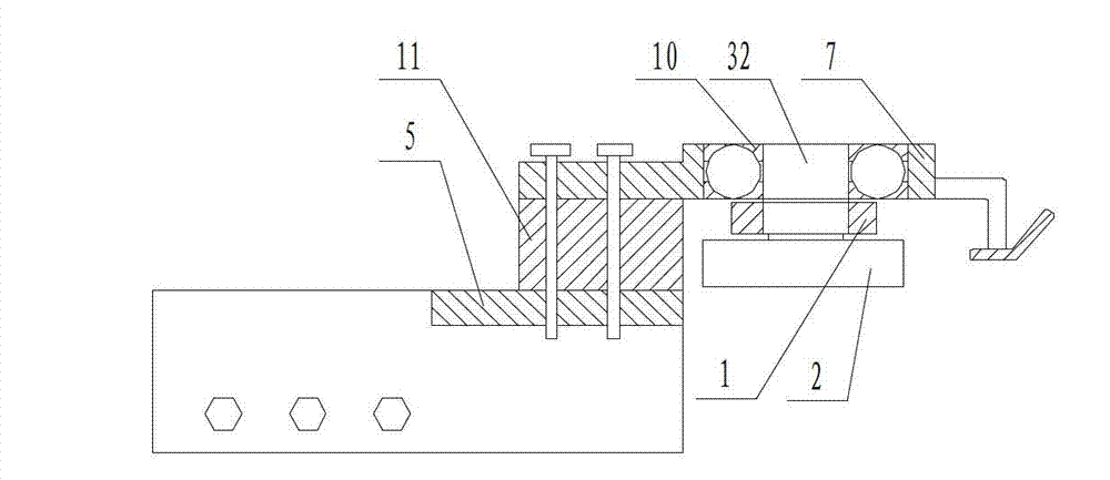
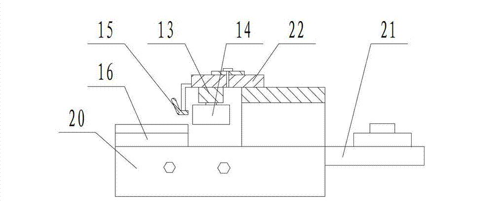
[0018] 1. Main support rod A; 2. Bearing group A; 3. Leaning plate; 4. Lateral support; 5. Longitudinal support; 6. Adjustable pitch bolt; 7. Connecting component; 8. Support bearing; 9. 10. Connecting rod A; 10. Positioning bearing; 11. Connecting pad; 12. Adjusting seat; 13. Main support rod B; 14. Bearing group B; 15. Side gauge pressure plate; 16. Bracket; 17. Transverse support groove 18. Mounting block; 19. Transverse support B; 20. Transverse support C; 21. Longitudinal support B; 22. Connecting component B; 23. Fixed seat; 24. Fixed seat slot; 25. Spring; 26. Moving rod; 27. Connecting rod B; 28. Pitch bearing; 29. ​​Support bearing B; 30. Connecting shaft A; 31. Connecting shaft B; 32. Connecting shaft C.

[0019] 101. Leaning; 102. Side gauge; 103. Volute iron; 104. Frame of printing machine; 105. Guide rail of printing machine.

[0020] Such as Figure...


PUM


Abstract

The invention relates to a volute iron printing side mark device of an iron printing machine, which belongs to the field of iron printing equipment, and is mainly used for solving the problems of low utilization ratio of raw materials and increased labor cost because the conventional iron-printing equipment of the prior art cannot normally and accurately print volute irons. The volute iron printing side mark device is realized through the following technical scheme that the volute iron printing side mark device comprises a leaning body and a side mark, wherein the leaning body comprises a main support rod A, a lateral support A, a longitudinal support A and a space regulation device, and a bearing pack A is installed on the main support rod A, is connected with a pressing plate of the leaning body through a connecting rod A and is connected with the longitudinal support A through a connecting part A; and the side mark comprises a main support rod B, a lateral support B, a longitudinal support B and a pressing regulation device, wherein a bearing pack B is fixedly installed on the main support rod B, is connected with the pressing plate of the side mark through a connecting rod B and is connected with the longitudinal support B through a connecting part B. The volute iron printing side mark device is mainly used in the volute iron printing equipment.

Description

technical field [0001] The invention belongs to the field of iron printing equipment, and more specifically relates to a printing side gauge device for a scroll iron printing machine. Background technique [0002] The printing patterns of traditional bottle cap patterns are mostly circular. In order to maximize the utilization rate of raw materials during printing, the circular printing patterns are mostly insertable typesetting during typesetting. But it still causes the waste of half circular patterns at the two ends of each row of circular patterns when printing rectangular materials, so that the raw material utilization rate when printing circular bottle cap patterns cannot be maximized, and the production cost is increased; if Cutting the rectangular raw material into scroll iron according to the size of the pattern can improve the utilization rate of raw materials when printing circular patterns, but the existing traditional iron printing equipment cannot normally and ...

Claims


Application Information

Patent Timeline
IPC IPC(8): B41F17/00
Inventor 王德喜
Owner SHANDONG HUANQIU TINPLATE CAN MAKING
Why Eureka
Try Eureka