Electromagnetic type magnetic rail brake

A magnetic rail brake, electromagnetic technology, applied in the direction of brakes, electromagnets, and railway braking systems where the braking element interacts with the track, etc., it can solve the problems of easy damage to the excitation coil, limited braking force of the magnetic rail brake, and terminal The internal cleaning protection device is not included in the working magnetic circuit, etc., so as to achieve the effect of reasonable magnetic circuit structure design, saving longitudinal space, and preventing damage to the coil

Inactive Publication Date: 2013-02-13
JIANGSU UNIV
View PDF6 Cites 12 Cited by
  • Summary
  • Abstract
  • Description
  • Claims
  • Application Information

AI Technical Summary

Problems solved by technology

[0004] The invention patent application has the following defects: each electromagnetic working circuit has two electromagnet excitations, and the end cleaning protection device is not included in the working magnetic circuit, that is, 2 n ( n ≥1, the same below) electromagnets only generate 2 electromagnetic working magnetic circuits, resulting in limited braking force of the magnetic track brake; there is no special protection facility for the excitation coil, which makes the excitation coil vulnerable to damage, while the protective shell of the traditional electromagnet is often With iron shell

Method used


Image

  • Electromagnetic type magnetic rail brake
  • Electromagnetic type magnetic rail brake
  • Electromagnetic type magnetic rail brake

Examples


Embodiment Construction

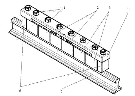
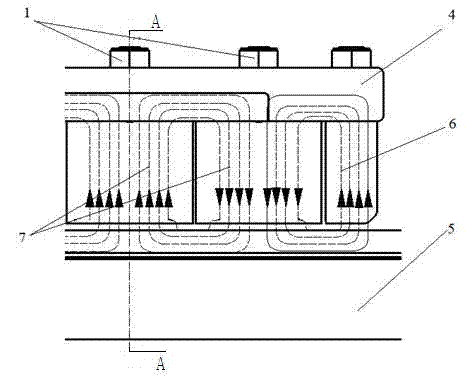
[0015] Such as Figure 1-2 As shown, the electromagnetic rail brake of the present invention is installed in pairs between the two wheels of the bogie on both sides of the rail vehicle, and an electromagnetic rail brake includes a longitudinal beam 4, and the longitudinal beam 4 is other parts and electromagnetic The basic component for connecting or installing the magnetic track brake; the longitudinal beam 4 is located on the upper part of the track 5, parallel to the track 5 and arranged along the longitudinal direction of the track, and is arranged in the longitudinal space between the track 5 and the longitudinal beam 4 m 3 electromagnets, m ≥2, the same below. This m A plurality of electromagnets 3 are distributed at equal intervals along the longitudinal direction of the track 5, each electromagnet 3 is directly above the track 5, and the axial direction of each electromagnet 3 is all vertically perpendicular to the track 5 and the longitudinal beam 4 at the same tim...


PUM


Abstract

The invention discloses an electromagnetic type magnetic rail brake, which is used for braking a railway vehicle when the railway vehicle runs. M electromagnets are equidistantly arranged in longitudinal space between rails and a longitudinal beam along the longitudinal direction of the rails, m is more than or equal to 2, the axial directions of the electromagnets are simultaneously perpendicular to the rails and the longitudinal beam, and two protecting stop blocks made of soft magnetic materials are symmetrically arranged at the two longitudinal ends of the longitudinal beam and are positioned between the longitudinal beam and the rails; opposite currents are inputted in each two optional adjacent electromagnets; the two protecting stop blocks and the two electromagnets which are closest to the protecting stop blocks form a magnetic circuit; the two electromagnets which are closest to the protecting stop blocks and the longitudinal beam form a magnetic circuit; the two electromagnets which are closest to the protecting stop blocks and the rails form a magnetic circuit; the two electromagnets which are closest to the protecting stop blocks and an air gap form a magnetic circuit; (m-1) closed working magnetic circuits consist of each two optional adjacent electromagnets, the longitudinal beam, the rails and the air gap; each two adjacent magnetic circuits share an electromagnet, and each electromagnet provides excitation for the two corresponding magnetic circuits; and the protecting stop blocks of which the ends have a protecting effect and the electromagnets adjacent to the protecting stop blocks form the magnetic circuits, so that the number of the electromagnets is reduced, the longitudinal space is saved, and the electromagnetic attraction is increased.

Description

technical field [0001] The invention relates to an electromagnetic magnetic rail brake, which belongs to the technical field of rail vehicle braking technology. Background technique [0002] The magnetic rail brake is a new type of brake developed to adapt to the popularization and high speed of rail vehicles. It mainly relies on the attraction of magnets and rails to generate sliding friction to decelerate rail vehicles. There are two main types of magnetic track brakes: permanent magnet type and electromagnetic type. The permanent magnet type magnetic track brake uses permanent magnets and does not need to consume energy during braking except for manipulation. Compared with permanent magnetic track brakes, electromagnetic track brakes do not require expensive rare earth permanent magnets, and have the characteristics of large braking force, simple maintenance, and convenient operation. For magnetic rail brakes, in order to obtain as large a braking force as possible in th...

Claims


Application Information

Patent Timeline
Patent Type & Authority Applications(China)
IPC IPC(8): B61H7/08H01F7/06
Inventor 陈士安顾宇峰何仁王胜赵廉健汤哲鹤
Owner JIANGSU UNIV
Why Eureka
Try Eureka