Non-compressed transformation dry powder pump

A dry powder pump, non-compression technology, applied in the direction of conveyors, transportation and packaging, conveying bulk materials, etc., can solve the problem of high failure frequency of variable pressure chambers, and achieve the effect of simple structure, low engineering cost and convenient installation

Inactive Publication Date: 2013-02-13
SOUTHEAST UNIV
View PDF5 Cites 3 Cited by
  • Summary
  • Abstract
  • Description
  • Claims
  • Application Information

AI Technical Summary

Problems solved by technology

[0003] Technical problem: The present invention aims at the problem that the frequent pressure changes of the existing variable pressure chamber body lead to high failure frequency of the variable pressure chamber, and proposes a non-compressive variable pressure dry powder pump with simple structure and high reliability.

Method used


Image

  • Non-compressed transformation dry powder pump
  • Non-compressed transformation dry powder pump
  • Non-compressed transformation dry powder pump

Examples


Embodiment Construction

[0022] The present invention will be further explained below in conjunction with the embodiments and the accompanying drawings.

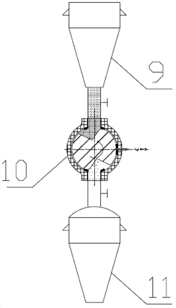
[0023] figure 1 It is a dry powder pressure-changing conveying system with this device. The powder enters the powder conveying system from the top of the normal-pressure silo 9, and is conveyed to the high-pressure silo 11 through the device 10 through variable pressure.

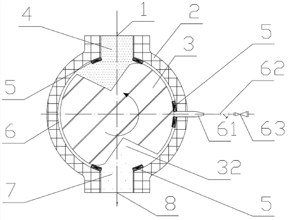
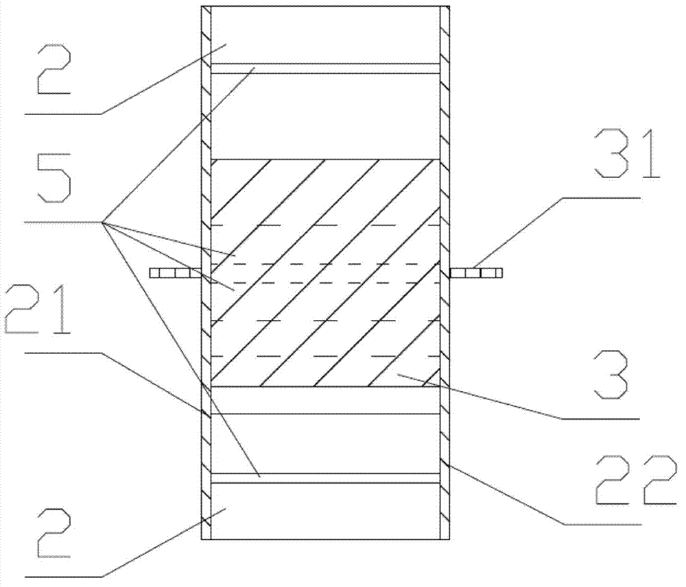
[0024] figure 2 It is the front sectional structure diagram of the variable pressure dry powder pump of the present invention. The pump body 2 is provided with a powder inlet 1, a powder suction chamber 4, a sealing table 5, a rotor chamber 6, an exhaust pipe 61, a filter 62, and a pressure reducing valve. 63, powder pressing chamber 7 and powder discharge outlet 8. Rotor chamber 6 is provided with rotor 3, and rotor 3 is connected with rotating shaft 31, and rotating shaft 31 is connected on pump body front end cover 21 and rear end cover 22, and rotating shaft 31 provides pow...


PUM


Abstract

The invention discloses a non-compressed transformation dry powder pump. A pump body is provided with a powder inlet, a powder absorption chamber, a rotor cavity, a press-powder cavity and a powder discharge outlet, which are sequentially connected from top to bottom; front and rear end covers are arranged at the front and rear parts of the rotor cavity to seal the rotor cavity; the rotating shaft of the rotor is horizontally arranged; the front end rear ends are respectively arranged on the front end cover and the rear end cover; an exhaust system is arranged on the cavity body at one side of the rotor cavity; the rotor cavity is provided with six sealing tables; the sealing tables are divided into three groups and respectively arranged at the inner walls adjacent with the powder absorption chamber, the press-powder cavity and an exhaust pipe; the sections of two gaps on the rotor are of sectors; the sector top angle is greater than 15 degrees; the sector arc length is smaller than the arc length between the exhaust pipe and the press-powder cavity; and extensible members stretching along the radial direction of the rotor are arranged on the sealing tables. The non-compressed transformation dry powder pump is simple, safe and reliable in structure, can replace a transformation warehouse in a pneumatic conveying system, and avoids a fussy design of the transformation warehouse.

Description

technical field [0001] The invention belongs to the field of clean coal power generation and chemical industry, and relates to equipment for high-pressure dense-phase pneumatic conveying. Background technique [0002] Today, pneumatic conveying systems are widely used in chemical, energy and other industries. In the high-pressure dense-phase pneumatic conveying system, a variable pressure chamber is used to pressurize the pulverized coal gas flow at atmospheric pressure. Since the variable pressure chamber is connected to the low-pressure powder silo and the high-pressure conveying silo, and it needs to switch between low pressure and high pressure frequently during its operation, the working environment of the variable pressure chamber is very harsh and prone to failure. Lock bucket tanks are prone to "bridging" phenomenon during the feeding process, resulting in poor feeding, which affects the efficiency of pneumatic conveying and will lead to discontinuity of pulverized ...

Claims


Application Information

Patent Timeline
Patent Type & Authority Applications(China)
IPC IPC(8): B65G53/58
Inventor 梁财陈晓平沈骝赵长遂刘道银
Owner SOUTHEAST UNIV
Why Eureka
Try Eureka