Frame structure for bridge type and door type combination type crane

A frame structure and combined technology, which is applied in the direction of walking bridge cranes, cranes, bottom support structures, etc., can solve problems such as weak wind resistance, earthquake resistance, poor coordination, and large working blind areas, so as to improve wind resistance and The effect of earthquake resistance, low manufacturing cost and short production cycle

Inactive Publication Date: 2013-02-13
ZHONGCHUAN NO 9 DESIGN & RES INST
View PDF7 Cites 1 Cited by
  • Summary
  • Abstract
  • Description
  • Claims
  • Application Information

AI Technical Summary

Problems solved by technology

[0003] At present, when lifting and transporting large pieces in docks and docks, a single or two gantry cranes or bridge cranes are generally used for lifting operations. It is necessary to build an elevated trestle along the wharf for the operation of a single or two bridge cranes; while lifting a gantry crane, a relatively large safety distance needs to be left, and at the same time, the weak coordination between the two cranes during lifting operations will Detrimental impact on the structure, the wind and earthquake resistance of a single portal frame structure is relatively weak
[0004] The prior art has the following disadvantages: (1) it is necessary to build an elevated trestle along the dock wall or the wharf for the operation of a single or two bridge cranes, and even if conditions permit, the basic investment needs to be increased; (2) two gantry cranes or bridge cranes Crane lifting has poor coordination and increased management difficulty; (3) two gantry or bridge cranes are affected by the length of the operating mechanism, their own structure and the track, and the two cranes require a large safety distance, resulting in a large working blind spot; (4) single The overall stability of the equipment is relatively poor, and the ability to resist storms and earthquakes is relatively weak

Method used


Image

  • Frame structure for bridge type and door type combination type crane
  • Frame structure for bridge type and door type combination type crane
  • Frame structure for bridge type and door type combination type crane

Examples


Embodiment Construction

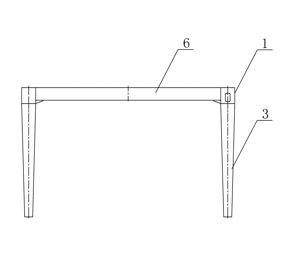
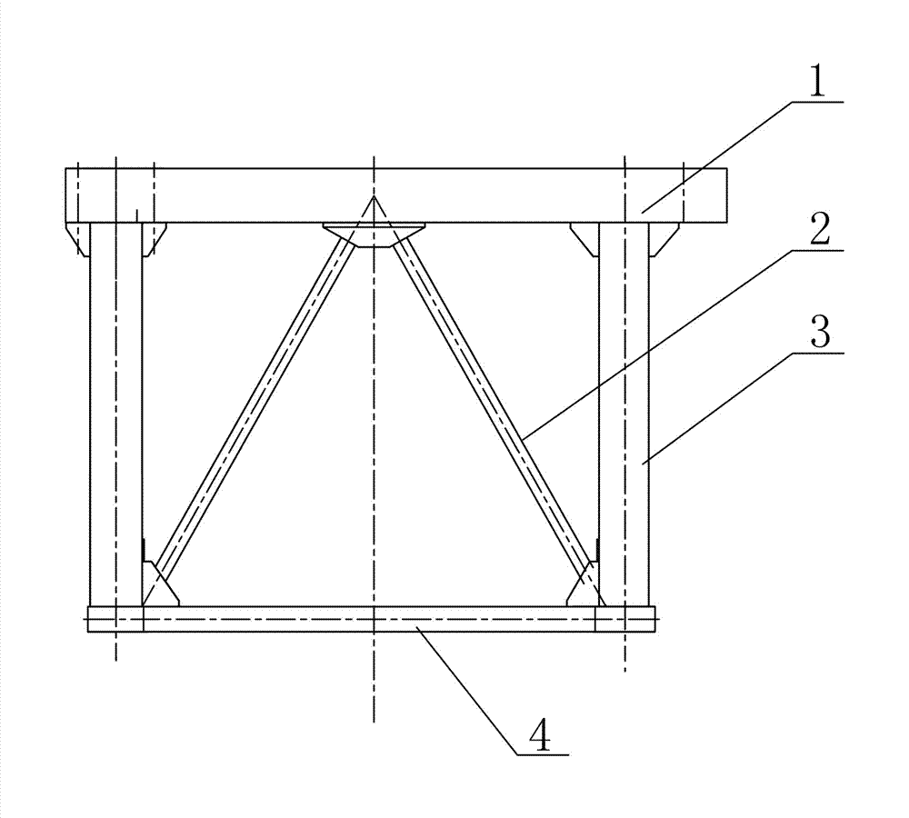
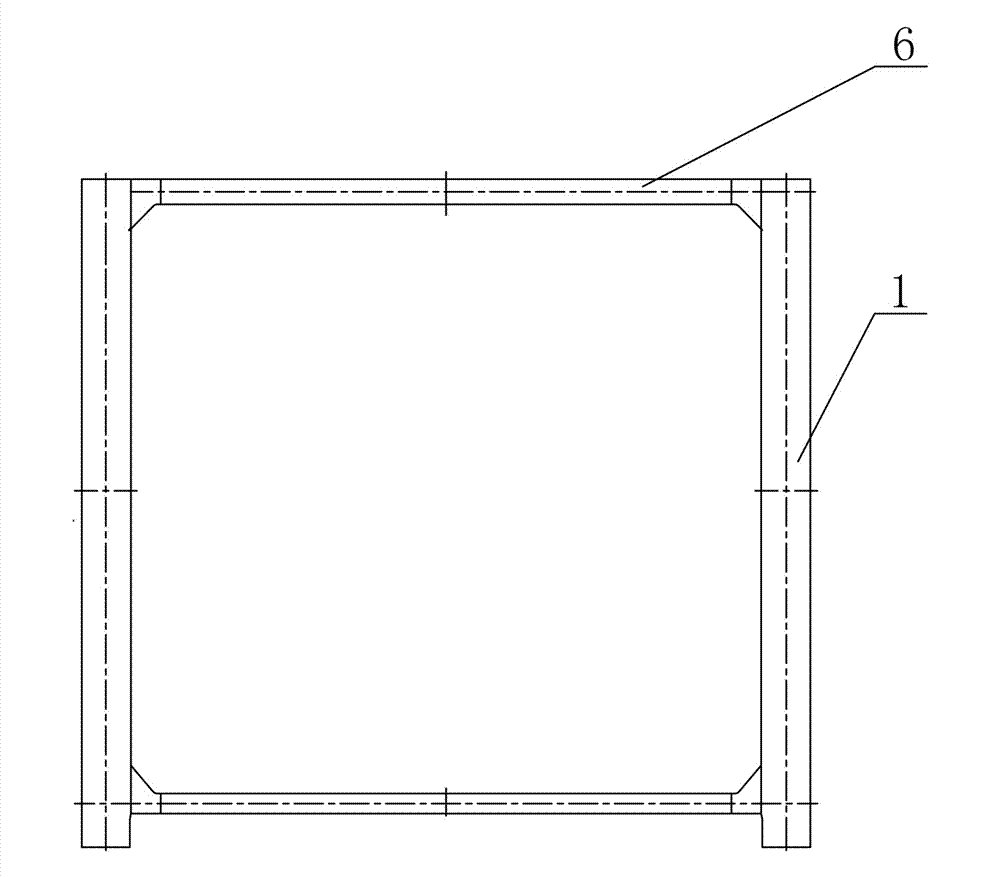
[0012] See attached figure 1 ~ attached image 3 , the present invention is welded by rail beam 1, oblique support 2, column leg 3, lower beam 4 and connection beam 6, described rail beam 1 and lower beam 4 are welded with two column legs 3 to form a side frame, and oblique support 2 is formed by welding The triangle is fixedly arranged between the track beam 1 and the lower beam 4, and the frame on both sides is welded by two connecting beams 6 to form a door frame-shaped steel structure; the track beam 1 and the connecting beam 6 are welded to form an upper plane frame; the track beam 1 is A box-shaped beam, which is provided with a working channel and a lighting system; the column leg 3 is a box-shaped column structure, and an escalator or a manned elevator connected with the track beam 1 is provided inside; the two ends of the inclined support 2 are provided with A connecting plate 8 is welded with the track beam 1 and the lower beam 4.

[0013] See attached Figure 4 ,...


PUM


Abstract

The invention discloses a frame structure for a bridge type and a door type combination type crane. The frame structure for the bridge type and the door type combination type crane is characterized by being formed by welding of a rail beam, inclined supports, pillar legs, a lower beam and contact beams. A lateral face framework is formed by welding of the rail beam, the lower beam and two pillar legs, and two lateral face frameworks form a doorframe type steel structure by welding of two contact beams. An upper plane framework is formed by welding of the rail beam and the contact beams, and the rail beam is a box type beam which is provided with a working channel and an illuminating system. The pillar legs are of box type pillar structures, and staircases or manned elevators which are arranged in the box type pillar structures are communicated with the rail beam. Compared with the prior art, the frame structure for the bridge type and the door type combination type crane is simple in structure, low in manufacturing cost, and convenient to install and maintain, avoids deformation of a structure due to non-synchronous operation, and particularly is suitable for a dockyard and a dock basin wharf, wherein a long-distance elevated trestle can not be arranged at the dockyard and the dock basin wharf.

Description

technical field [0001] The invention relates to the technical field of crane construction and installation, in particular to a frame structure used for bridge and gantry combined cranes in docks and docks. Background technique [0002] As the key component of the crane, the metal structure has developed correspondingly with the diversified needs of the crane's functional form, but the requirements for the structure to meet the functionality and equipment safety remain unchanged. [0003] At present, when lifting and transporting large pieces in docks and docks, a single or two gantry cranes or bridge cranes are generally used for lifting operations. It is necessary to build an elevated trestle along the wharf for the operation of a single or two bridge cranes; while lifting a gantry crane, a relatively large safety distance needs to be left, and at the same time, the weak coordination between the two cranes during lifting operations will It has a negative impact on the stru...

Claims


Application Information

Patent Timeline
Patent Type & Authority Applications(China)
IPC IPC(8): B66C17/04B66C5/02
Inventor 严旭东张勇李永凤茅金龙杨国光刘涛伟董胜龙董元跃俞永其黄之涛
Owner ZHONGCHUAN NO 9 DESIGN & RES INST
Why Eureka
Try Eureka