

Material discharge device for vertical furnace
A technology for shaft furnaces and material tanks, applied to shaft furnaces, furnaces, furnace types, etc., can solve problems such as difficulty in discharging materials, achieve the effects of reducing maintenance costs, continuous and efficient operation, and saving maintenance time
Inactive Publication Date: 2013-02-13
CISDI ENG CO LTD
View PDF7 Cites 4 Cited by
- Summary
- Abstract
- Description
- Claims
- Application Information
AI Technical Summary
Problems solved by technology
The shaft furnace is continuous discharge, which is relatively easy for the shaft furnace operated under normal pressure, but it is more difficult for the shaft furnace operated under pressure
Method used
View moreImage
Smart ImageViewing Examples

Examples
Embodiment 2
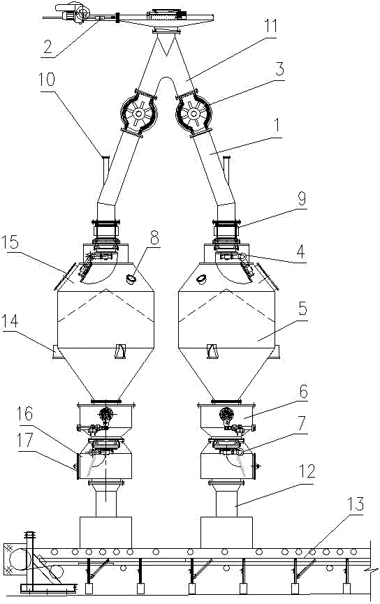
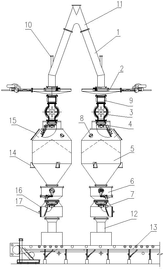
[0041] Embodiment 2: In the shaft furnace discharge device of this embodiment, the gate valve 2 is arranged at the inlet of the feeding pipe, and the outlet of the distribution pipe 1 is connected to the inlet of the upper sealing valve 4 through a bellows 9; in this embodiment Other structures of the shaft furnace discharging device are the same as in the first embodiment, and its working process is also the same as in the first embodiment.
Login to View More PUM
 Abstract
The invention discloses a material discharge device for a vertical furnace, comprising a material blanking pipe, a gate valve, a rotating material discharge valve, an upper sealing valve, a discharged material tank, a material flow regulating valve and a lower sealing valve. The material discharge pipe is provided with at least two material dividing pipes; the gate valve is arranged at the inlet of the material discharge pipe or the outlets of the material dividing pipes; the rotating material discharge valve is arranged on the material dividing pipes and below the gate valve; the upper sealing valve is connected with the outlet of the rotating material discharge valve or the outlets of the material dividing pipes; the discharged material tank is connected with the outlet of the upper sealing valve; the material flow regulating valve is connected with the outlet of the discharged material tank; the lower sealing valve is connected with the outlet of the material flow regulating valve; and the discharged material tank is provided with a uniform pressure discharge interface. Due to the alternative work of equipment on the material flow paths of the material dividing pipes, the furnace material can be discharged continuously, and the vertical furnace can work continuously and efficiently. As the discharged material tank is provided with the uniform pressure discharge interface, the vertical furnace can discharge materials smoothly under pressure or normal pressure, and the material discharge device can work reliably and stably. The equipment in the material discharge device adopts the module design and can be repaired independently, so that the repair time is saved, and the maintenance cost is reduced.
Description
technical field [0001] The invention relates to the technical field of ironmaking equipment, in particular to a discharge system of a shaft furnace. Background technique [0002] Due to its stable composition, low harmful impurities, uniform particle size and many other advantages, direct reduced iron plays an increasingly important role in the field of iron and steel metallurgy. In recent years, the growth rate of global direct reduced iron production has reached 9%, which shows that its development potential is quite huge. There are many kinds of direct reduced iron production techniques, among which the gas-based shaft furnace is the mainstream technology, and the output of direct reduced iron has accounted for about 75% of the total output. [0003] The shaft furnace discharge device is the key equipment of the direct reduction shaft furnace, and its working performance directly affects whether the shaft furnace can produce normally. The shaft furnace is continuous dis...
Claims
Login to View More Application Information
Patent Timeline
 Patent Type & AuthorityApplications(China)
IPC IPC(8): C21B13/02
Inventor王蜀生王涛戴文军郑军张涛郭敏陈凌
OwnerCISDI ENG CO LTD