Concrete hollow slab bridge strengthened by transverse integral clamping connection

A hollow slab bridge and concrete technology, applied in the direction of bridge reinforcement, bridges, bridge parts, etc., can solve the problems of increased lateral distribution coefficient of veneer load, disadvantageous, disadvantageous quality, etc. Avoid the effect of stress on the veneer

Inactive Publication Date: 2013-02-13
商丘市豫东公路勘察设计有限公司
View PDF6 Cites 19 Cited by
  • Summary
  • Abstract
  • Description
  • Claims
  • Application Information

AI Technical Summary

Problems solved by technology

[0002] Concrete hollow slab bridge is a kind of bridge with hollow slab spanning structure along the bridge direction. It has the advantages of convenient construction, low engineering cost and standardized centralized prefabrication production. However, concrete hollow slab bridges are prone to structural defects. Caused by the destruction of the hinge joint between the plate and the plate, the bite force between the plate and the plate is greatly reduced, the force transmission effect is greatly reduced, and the lateral distribution coefficient of the single plate load is increased. When the hinge joint is completely destroyed, the most unfavorable The stress state of the veneer
[0003] At present, the diseases of hollow slab bridges are mainly fixed on both sides of the repaired bridge vertically with splints, and then the splints on both sides are stretched through the bridge bottom surface or transversely through the interior of the bridge to realize the hollow slab. The external or interna

Method used


Image

  • Concrete hollow slab bridge strengthened by transverse integral clamping connection
  • Concrete hollow slab bridge strengthened by transverse integral clamping connection
  • Concrete hollow slab bridge strengthened by transverse integral clamping connection

Examples


Embodiment Construction

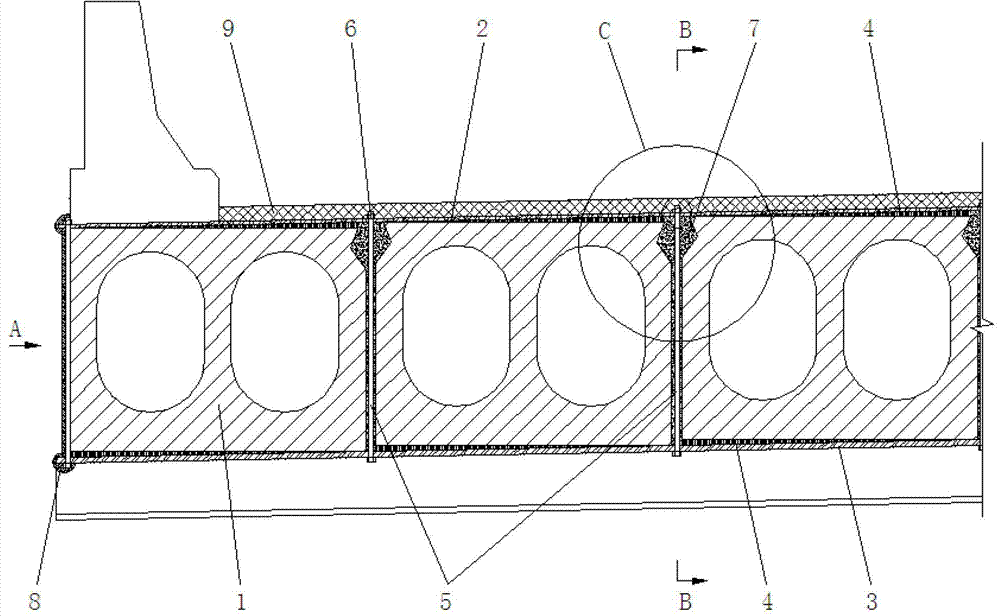
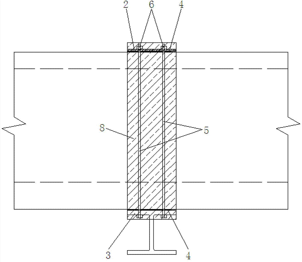
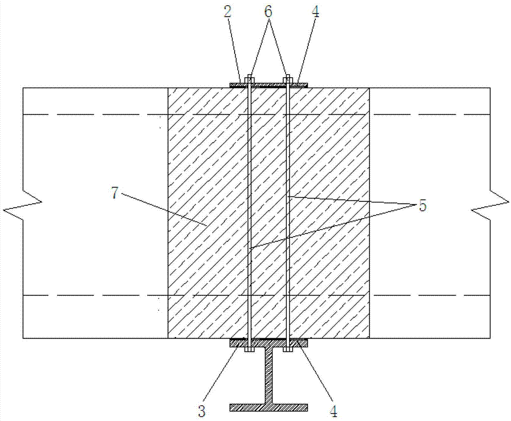
[0021] figure 1 It is a structural schematic diagram of the present invention, figure 2 for figure 1 Partial view of A, image 3 for figure 1 Sectional view at B-B, Figure 4 for figure 1 The enlarged view at C of , as shown in the figure: the concrete hollow slab bridge reinforced by transverse overall clamping in this embodiment includes a hollow slab girder, an upper reinforcement 2, a lower reinforcement 3 and connectors, and the hollow slab girder consists of The hollow plates 1 are arranged side by side. The upper reinforcement 2 and the lower reinforcement 3 are correspondingly arranged on the upper surface and the lower surface of the hollow plate girder. The upper reinforcement 2 and the lower reinforcement 3 are connected along the upper and lower Directional clamping is used to carry out horizontal overall clamping and reinforcement of the hollow slab girder, and the horizontal clamping of each hollow slab 1 through the upper reinforcement 2, the lower reinfor...


PUM


Abstract

The invention discloses a concrete hollow slab bridge strengthened by transverse integral clamping connection. The concrete hollow slab bridge comprises a hollow slab beam, upper strengthening parts, lower strengthening parts and connecting parts, wherein the hollow slab beam is formed by parallel arrangement of hollow slabs, upper strengthening parts and lower strengthening parts are arranged on the upper surface of the hollow slab beam and the lower surface of the hollow slab beam correspondingly, and upper strengthening parts and lower strengthening parts are clamped along an upper direction and a lower direction through connecting parts so as to conduct transverse integral clamping connection strengthening on the hollow slab beam. According to the concrete hollow slab bridge strengthened by transverse integral clamping connection, hollow slabs are clamped into a whole transversely through pairs of strengthening parts which are arranged on top surfaces of hollow slabs and bottom surfaces of hollow slabs and connecting parts which are fixedly connected between corresponding upper strengthening parts and lower strengthening parts, so that the transverse integral strengthening of the concrete hollow slab bridge is achieved, the transverse integral structure performance of the concrete hollow slab bridge can be effectively improved, single-plate stressing is avoided, the implementation is convenient, the quality can be guaranteed, and the service life of the bridge can be prolonged.

Description

technical field [0001] The invention relates to a bridge construction, in particular to a concrete hollow slab bridge reinforced by transverse integral clamping. Background technique [0002] Concrete hollow slab bridge is a kind of bridge with hollow slab spanning structure along the bridge direction. It has the advantages of convenient construction, low engineering cost and standardized centralized prefabrication production. However, concrete hollow slab bridges are prone to structural defects. Caused by the destruction of the hinge joint between the plate and the plate, the bite force between the plate and the plate is greatly reduced, the force transmission effect is greatly reduced, and the lateral distribution coefficient of the single plate load is increased. When the hinge joint is completely destroyed, the most unfavorable The stress state of the veneer. [0003] At present, the diseases of hollow slab bridges are mainly fixed on both sides of the repaired bridge v...

Claims


Application Information

Patent Timeline
IPC IPC(8): E01D22/00E01D19/00
Inventor 刘祖祥周志祥华学礼
Owner 商丘市豫东公路勘察设计有限公司
Why Eureka
Try Eureka