
Assembled type concrete block pressing rod beam and using method, production die and production method thereof

An assembly method and concrete technology, which are applied in the directions of molds, earthwork drilling, roof beams for supporting mine roofs, etc., can solve the problems of excessive labor, long construction period, unfavorable environment, etc. The effect of short and simple construction process

Inactive Publication Date: 2015-02-11
福州市第三建筑工程公司
View PDF8 Cites 0 Cited by
  • Summary
  • Abstract
  • Description
  • Claims
  • Application Information

AI Technical Summary

Problems solved by technology

[0002] In deep underground support projects, when the external pull is not available, the surrounding protection body needs to adopt the internal support design, which is mainly carried by the horizontal force member compression bar beam, and the longer the length, the more stable the pressure bearing requirement. However, mechanical excavation requires that the length of compression bars or beams must meet the construction requirements. Usually, it is difficult to support compression beams with criss-cross layer steel pipe tools. Most of them can only use solid cast-in-place reinforced concrete compression beams. After the operation, it has to be discarded, resulting in a lot of labor to disassemble the support body, which is troublesome, takes a long time, is expensive, and has an adverse impact on the environment.

Method used


Image

  • Assembled type concrete block pressing rod beam and using method, production die and production method thereof
  • Assembled type concrete block pressing rod beam and using method, production die and production method thereof
  • Assembled type concrete block pressing rod beam and using method, production die and production method thereof

Examples


Embodiment Construction

[0031] In order to describe the technical content, structural features, achieved goals and effects of the present invention in detail, the following will be described in detail in conjunction with the embodiments and accompanying drawings.

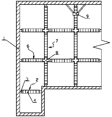
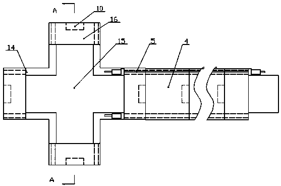
[0032] like figure 1 and 2 As shown, an assembled concrete block compression bar beam assembled with prestressed steel bars includes a single beam 2 and a well-shaped beam, and the single beam includes two end blocks 3, several middle blocks 4 and at least four prestressed steel bars 5. The blocks at both ends and several middle blocks are connected into a whole through prestressed steel bars; One end of the bar beam 6 is connected to the node block 8, and the other end is supported on the supporting body 1; Supporting columns are provided, and the end-span compression bar beam includes an end block 3, several intermediate blocks 4 and at least four prestressed steel bars 5 for connecting these intermediate blocks 4 in series, and the in...


PUM


Abstract

The invention relates to an assembled type concrete block pressing rod beam and a using method, production die and production method thereof. The pressing rod beam comprises a single beam and a cross beam, wherein the single beam comprises two end blocks, a plurality of middle blocks and at least four pre-stress steel bars; the two end blocks and the middle blocks are connected in series into a whole through the pre-stress steel bars; the cross beam comprises an end span pressing rod beam, a middle span pressing rod beam and a node block; one end of the end span pressing rod beam is connected to the node block, and the other end of the end span pressing rod beam supports a supporting and protecting body; two ends of the middle span pressing rod beam are respectively connected with the node block; a supporting vertical column is arranged below the node block; the end span pressing rod beam comprises the end blocks, a plurality of middle blocks and at least four pre-stress steel bars for connecting the middle blocks in series; and the middle span pressing rod beam comprises a plurality of middle blocks and at least four pre-stress steel bars for connecting the middle blocks in series. The pressing rod beam is extremely low in manufacturing cost, simple in construction process and short in working period and causes no side effect on the environment.

Description

technical field [0001] The invention relates to an assembled concrete block compression bar beam assembled with prestressed steel bars, a use method, a production mold and a production method. Background technique [0002] In deep underground support projects, when the external pull is not available, the surrounding protection body needs to adopt the internal support design, which is mainly carried by the horizontal force member compression bar beam, and the longer the length, the more stable the pressure bearing requirement. However, mechanical excavation requires that the length of compression bars or beams must meet the construction requirements. Usually, it is difficult to support compression beams with criss-cross layer steel pipe tools. Most of them can only use solid cast-in-place reinforced concrete compression beams. After the operation, it has to be discarded again, resulting in a lot of labor for dismantling the supporting body, which is troublesome, takes a long ...

Claims


Application Information

Patent Timeline
Patent Type & Authority Patents(China)
IPC IPC(8): E21D17/00E21D17/10B28B7/22
Inventor 肖纹籛肖斯熔肖斯昕
Owner 福州市第三建筑工程公司
Learn More