Gas compressor end sealing structure of turbocharger

A compressor end seal, turbocharger technology, applied in the direction of machines/engines, mechanical equipment, engine components, etc., can solve problems such as large gaps, lubricating oil leakage, axial movement, etc., to prevent axial movement dynamic and radial displacement, prevent gap leakage, good sealing effect

Active Publication Date: 2013-02-13
HUNAN TYEN MACHINERY
View PDF9 Cites 3 Cited by
  • Summary
  • Abstract
  • Description
  • Claims
  • Application Information

AI Technical Summary

Problems solved by technology

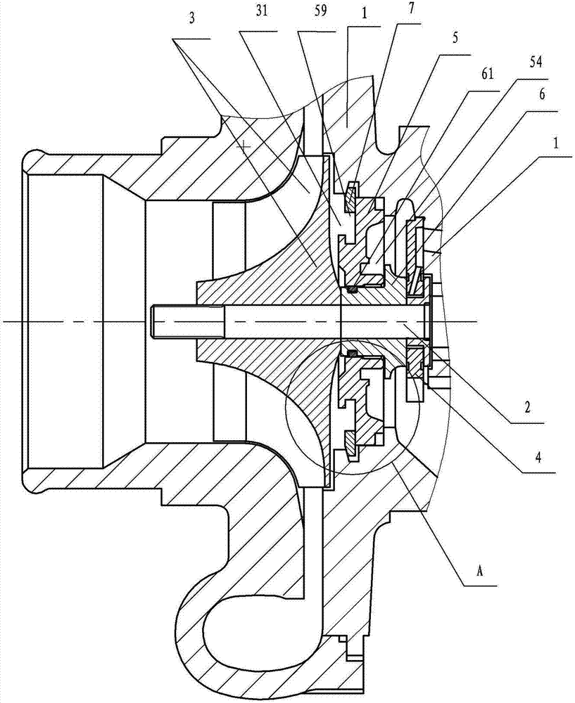
[0004] Outer side of oil seal cap 5 (from figure 1 It refers to the right side) the edge is provided with an edge annular gap 59, the inner cavity of the bearing body 1 is provided with a slot 12 corresponding to the position of the oil seal cap 5; the retaining ring 7 is snapped into the slot 12 of the bearing body 1 and blocks Outside the edge annular notch 59 on the outside of the oil seal cap 5, the retaining ring 7 can block the oil seal cap 5 to the right, that is, it can limit the movement of the oil seal cap 5 in the direction of the compressor impeller 3 in the axial direction (indirectly, it can also limit The thrust bearing 4 and the seal sleeve 6 move axially toward the compressor impeller 3), although the retaining ring 7 can 
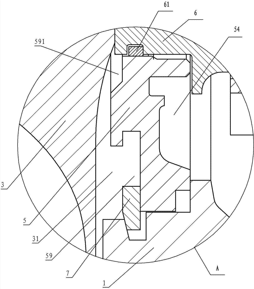
restrict the axial movement of the oil sealing cap 5 toward the compressor impeller 3 to a certain extent, the oil sealing cap 5 has a certain However, since the retaining ring 7 itself is only clamped in the slot 12 of the bearing body 1, it cannot be completely fixed, and certain axial movement and radial displacement will occur, so that the oil seal cap 5 and the sealing sleeve 6 The position between the oil seal cap 5 and the seal sleeve 6 is unstable, which causes the gap size between the oil seal cap 5 and the seal sleeve 6 to change continuously (during operation), which affects the sealing effect between the oil seal cap 5 and the seal sleeve 6, that is, the lubricating oil will easily flow from the The mounting hole of the oil seal cap 5 leaks outward, and due to the radial displacement of the oil seal cap 5, lubricating oil will leak out from between the outer circumference of the oil seal cap 5 and the bearing body 1, so it is fixed by the retaining ring 7 There will be a serious oil leakage problem in the oil seal cap 5
[0005] The side of the oil seal cap 5 close to the compressor impeller 3 is provided with an edge annular notch 59 with a cross-section approximately rectangular, although it brings convenience for installing the retaining ring 7 (a space is reserved for the installation of the retaining ring 7), but it makes the oil seal cap 5 and the wheel back of the compressor impeller 3 form a large annular air storage chamber 31 with a cross-section approximately rectangular. When a small amount of air with a certain pressure is introduced from the outlet of the compressor impeller 3 for storage, it is used to prevent lubricating oil from leaking. Tests have proved that when the engine is working at partial load or low load, especially when the car engine is dragging backwards on a long slope in plateau areas, the annular air storage chamber 31 with a nearly rectangular cross-section has a large space, and it is difficult to fill the annular space with a small amount of air. Air storage chamber 31, the air pressure stored in the annular air storage chamber 31, which is approximately rectangular in cross-section, is relatively low, that is, a large negative pressure cavity is formed behind the wheel of the compressor impeller 3, and it is easy for lubricating oil to leak through the oil sealing cap 5 come out
[0006] There is a central annular gap 591 on the outer surface of the oil sealing cap 5 close to the installation hole (close to the back of the compressor impeller), resulting in a gap between the outer surface of the oil sealing cap 5 near the installation hole and the compressor impeller 3. The gap between them is very large, and the negative pressure on the back of the compressor impeller 3 (especially when the engine is working at part load or low load, especially when the car engine is dragged backwards on a long slope in plateau areas) can easily penetrate the oil seal cap 5 The inner side causes the problem of oil leakage, that is, the gap is too large. When negative pressure is formed on the back of the compressor impeller 3, due to the wide channel formed by the gap, the air between the oil seal cap 5 and the sealing sleeve 6 will immediately enter the compressor impeller 3 The negative pressure cavity on the back of the compressor impeller 3, so that the lubricating oil between the oil seal cap 5 and the sealing sleeve 6 can easily leak to the negative pressure cavity on the back of the compressor impeller 3, resulting in oil leakage
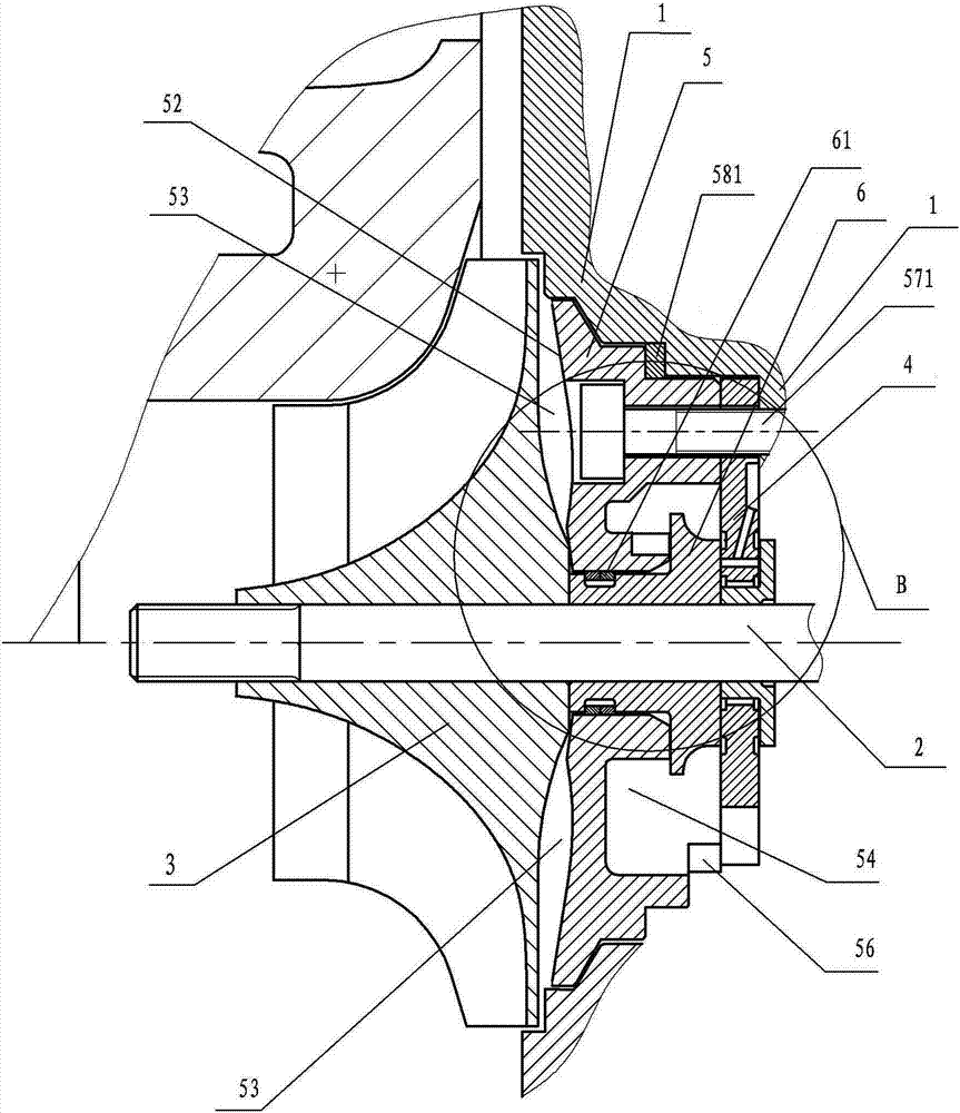
[0007] The inner side of the oil sealing cap 5 is provided with a recessed annular drainage cavity 54. Although the drainage cavity 54 has a certain drainage effect, it can introduce lubricating oil into the interface between the oil sealing cap 5 and the sealing sleeve 6, and the oil sealing cap 5 and the sealing sleeve The sleeve 6 and other parts are lubricated, but the annular drainage chamber 54 has no oil storage function. When the engine is just started, when the lubricating oil does not enter the oil chamber of the bearing body 1, the annular drainage chamber 54 naturally does not have lubricating oil yet, and the oil seal There is no oil film between the cover 5 and the sealing sleeve 6, which causes the parts such as the oil sealing cover 5 and the sealing sleeve 6 to be in a state of "dry friction", which is easy to damage the oil sealing cover 5 and the sealing sleeve 6, and at the same time causes more serious damage. oil spill problem

Method used


Image

  • Gas compressor end sealing structure of turbocharger
  • Gas compressor end sealing structure of turbocharger
  • Gas compressor end sealing structure of turbocharger

Examples


Embodiment 1

[0031] Such as Figure 3-7 Shown: a compressor end sealing structure of a turbocharger, which includes a bearing body 1, a rotor 2, a compressor impeller 3, a thrust bearing 4, an oil seal cover 5 and a seal sleeve 6; the rotor 2 is the main shaft, and its It is the common rotating shaft of the compressor of the turbocharger and the supercharger; the seal sleeve 6 is installed on the rotor 2 and is located between the compressor impeller 3 and the thrust bearing 4; the oil seal cover 5 is provided with a mounting hole 51 (such as Figure 6-7 As shown), the oil seal cover 5 is installed on the seal sleeve 6 through the installation hole 51, and it is a dynamic fit with the seal sleeve 6, that is, the seal sleeve 6 can rotate in the installation hole 51 of the oil seal cover 5 together with the rotor 2 , there is a sealing ring 61 between the oil sealing cap 5 and the sealing sleeve 6, and the sealing ring 61 is a double sealing ring (two sealing rings) to block the lubricating ...


PUM


Abstract

The invention discloses a gas compressor end sealing structure of a turbocharger. The gas compressor end sealing structure comprises a bearing body (1), a rotator (2), a gas compressor impeller (3), a thrust bearing (4), a sealing oil cover (5) and a sealing sleeve (6), wherein a screw hole (57) is arranged on the sealing oil cover (5); the sealing oil cover (5) is fixedly arranged on the bearing body (1) through a bolt (571); the outside surface (52) of the sealing oil cover (5) is a concave surface; the outside surface (52) of the sealing oil cover (5) is adjacent to the back surface of the gas compressor impeller (3) at a position close to an installation hole (51) of the sealing oil cover (5); and an oil storage cavity (55) for storing lubricating oil can be arranged at the upper part on the inner side wall of the annular guide cavity (54) of the sealing oil cover (5). The gas compressor end sealing structure is stable in internal structure and small in cavity of the outer side surface of the sealing oil cover, can supercharge and choke flow secondarily to form an oil film in advance. Moreover, the gas compressor end sealing structure is good in oil leakage resistance effect, can buffer axial force and can reduce starting friction and damages.

Description

technical field [0001] The invention relates to a turbocharger of an engine, in particular to a compressor end sealing structure of the turbocharger. Background technique [0002] At present, almost all diesel engines adopt turbocharging technology, and turbocharging technology is also being widely applied and promoted to gasoline engines. Turbochargers have become a key component of supercharged engine boosting systems. Users have higher and higher requirements on the power performance, economic performance, environmental protection performance and other parameters of the turbocharger matched with the engine. At present, the oil leakage problem of the turbocharger (mainly from the compressor end oil leakage). [0003] The lubrication structure and working principle of the compressor end of the turbocharger: such as figure 1 As shown, the lubricating oil enters the lubricating oil passage of the bearing body from the oil inlet of the bearing body 1 to lubricate and cool t...

Claims


Application Information

Patent Timeline
Patent Type & Authority Applications(China)
IPC IPC(8): F01D25/18F02B39/14
Inventor 欧永健王星吴玉堂徐金
Owner HUNAN TYEN MACHINERY
Why Eureka
Try Eureka