Vibrating diaphragm fan, mobile phone applying same and diaphragm vibrating and ventilating method

A technology for fans and mobile phones, applied in the field of ventilation devices, can solve the problems of poor thermal conductivity, crash, heat transfer, etc., and achieve the effects of good heat dissipation, simple structure and strong flexibility

Inactive Publication Date: 2013-02-13
赛龙通信技术(深圳)有限公司
View PDF8 Cites 11 Cited by
  • Summary
  • Abstract
  • Description
  • Claims
  • Application Information

AI Technical Summary

Problems solved by technology

This method needs to be realized through efficient heat transfer between the contact surfaces, and it is necessary to add plastic thermally conductive materials to fill the gaps, for example, to use thermally conductive silicone grease or graphene thermally conductive film, which will not only increase the cost but also complicate the production process
At the same time, in order to distribute the heat as evenly as possible and increase the heat dissipation surface, the metal plate used for heat conduction needs to have a certain thickness and area, which will also increase the cost and is not conducive to the thinning of the product
The structure of mobile phones is generally to install the display screen on the front and the battery on the back. The thermal conductivity of these two parts is relatively poor.
At the same time, the shell is mostly made of plastic, and its thermal conductivity is also poor.
Therefore, even if the heat is spread evenly inside the mobile phone by using passive heat dissipation, the heat cannot be transferred to the outside of the mobile phone well. The speed slows down or even crashes, affecting the performance of mobile phones

Method used


Image

  • Vibrating diaphragm fan, mobile phone applying same and diaphragm vibrating and ventilating method
  • Vibrating diaphragm fan, mobile phone applying same and diaphragm vibrating and ventilating method
  • Vibrating diaphragm fan, mobile phone applying same and diaphragm vibrating and ventilating method

Examples


Embodiment Construction

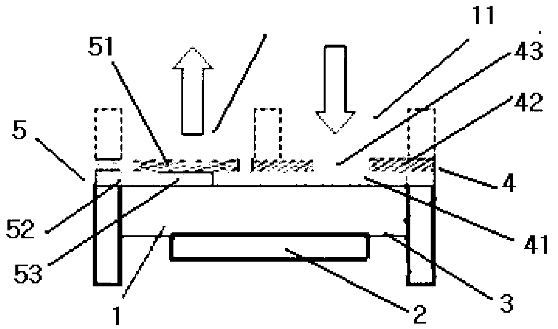
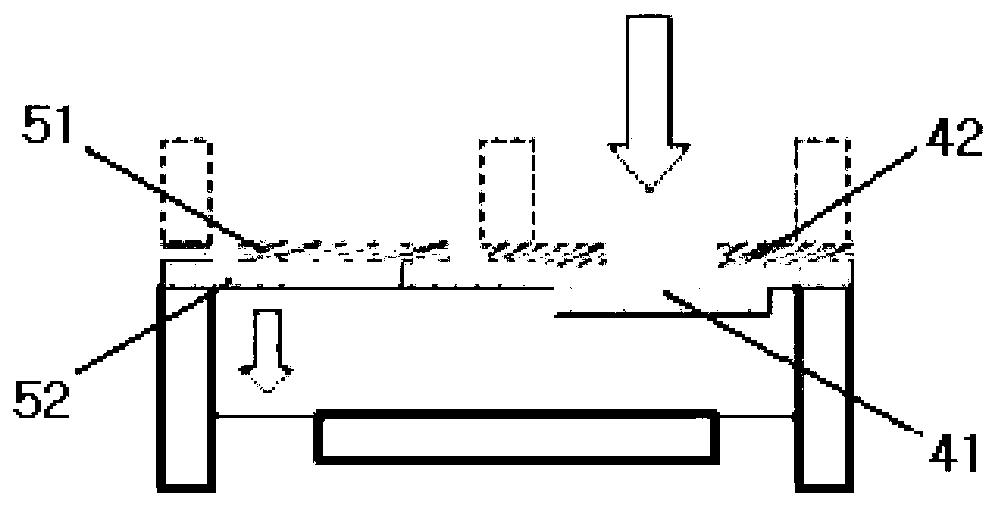
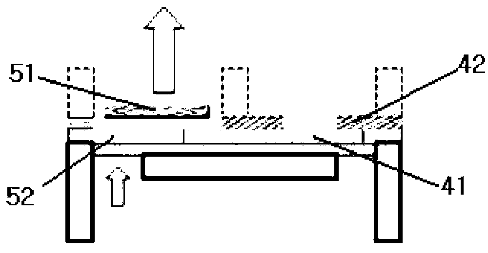
[0031] In order to make those skilled in the art better understand the technical solution of the present invention, the present invention will be further described in detail below in conjunction with the accompanying drawings, as Figure 1 to Figure 4 As shown, the diaphragm fan in Embodiment 1 of the present invention includes a closed cavity 1 and an electromagnetic coil 2. An active diaphragm 3, an air inlet rectifier 4 and more than one air outlet rectifier 5 are arranged in the closed cavity. The coil 2 is connected with the control circuit and installed integrally with the active diaphragm 3 to drive the active diaphragm 3 to vibrate. The circuit diagram is as follows Figure 5 As shown, by inputting a square wave signal with a frequency of F0, through the following driving circuit, the driving circuit forms a class AB audio amplifier through two amplifiers and several resistors and capacitors, and the input square wave is converted by the integral operation of C1 and R1 ...


PUM


Abstract

The invention discloses a vibrating diaphragm fan, a mobile phone applying the same and a diaphragm vibrating and ventilating method. The vibrating diaphragm fan comprises a sealed cavity and a vibrating component, wherein the sealed cavity is internally provided with a driving vibrating diaphragm, more than one incoming air rectifying sheet and more than one outgoing air rectifying sheet; the vibrating component is connected with a control circuit to drive the driving vibrating diaphragm to vibrate; the incoming air rectifying sheet is arranged at the place where an air inlet is and includes a driven vibrating diaphragm layer and a rectifying layer; the rectifying layer is arranged at the outer side and is provided with an air inlet hole; the driven vibrating diaphragm in a non-vibrating state is stuck tightly to seal the air inlet hole; the outgoing air rectifying sheet is arranged at the place where an air outlet is and includes a driven vibrating diaphragm layer and a rectifying layer; the rectifying layer is arranged at the inner side and is provided with an air outlet hole; the driven vibrating diaphragm when in a non-vibrating state is stuck tightly to seal the air outlet hole; and the driving vibrating diaphragm drives the driven vibrating diaphragm on the incoming air rectifying sheet or the outgoing air rectifying sheet to do reciprocating vibration through air, so that air is sucked or sent from the air inlet or air outlet of the rectifying layers.

Description

technical field [0001] The invention relates to the field of ventilation, in particular to ventilation devices for digital products such as mobile phones. Background technique [0002] Existing digital products, such as mobile phones, are getting smaller and higher in performance, and the problem of heat dissipation is becoming more and more prominent. Due to the limitation of structure and volume, it is difficult to install ordinary fans in mobile phones to achieve active heat dissipation. Therefore, the current The heat dissipation method is passive heat dissipation. The passive heat dissipation method is to conduct the heat from the central processing unit (CPU), memory (Memory) and other parts with high heat generation evenly to the metal plates around the fuselage through heat-conducting materials to achieve heat dissipation. This method needs to be realized through efficient heat transfer between the contact surfaces, and it is necessary to add plastic thermally conduc...

Claims


Application Information

Patent Timeline
Patent Type & Authority Applications(China)
IPC IPC(8): F04B45/04F04B49/06H04M1/02
Inventor 邓金荣罗彬刘文
Owner 赛龙通信技术(深圳)有限公司
Why Eureka
Try Eureka