Narrow band pass frequency selective surface

A frequency-selective surface, narrow-band technology, applied in circuits, waveguide-type devices, electrical components, etc., can solve the problems of complex structural design, limited application scope, unconsidered application, etc., to achieve flexible and adjustable position, high permeability, simple structure

Inactive Publication Date: 2015-01-07
SHANGHAI INST OF OPTICS & FINE MECHANICS CHINESE ACAD OF SCI
View PDF4 Cites 10 Cited by
  • Summary
  • Abstract
  • Description
  • Claims
  • Application Information

AI Technical Summary

Problems solved by technology

However, this structural design uses a metal structure with a high duty ratio (duty ratio>4) to realize the band-pass filtering function in the microwave frequency band, and does not consider the application in the optical window, that is, it cannot achieve high transparency in the visible to infrared band. limit its scope of application
[0005] 2. Patent 201310385578.9 "High-performance radar/infrared dual-band band-pass frequency selective surface" provides a high-performance radar/infrared dual-band band-pass FSS, including two layers of the same optically transparent FSS and the coupling between the two layers of optically transparent FSS Dielectric

Method used


Image

  • Narrow band pass frequency selective surface
  • Narrow band pass frequency selective surface
  • Narrow band pass frequency selective surface

Examples


Embodiment 1

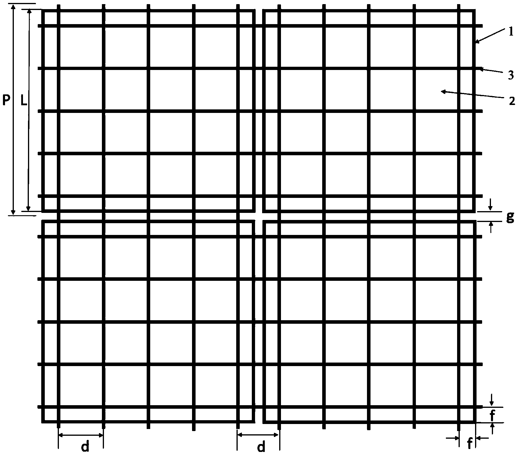
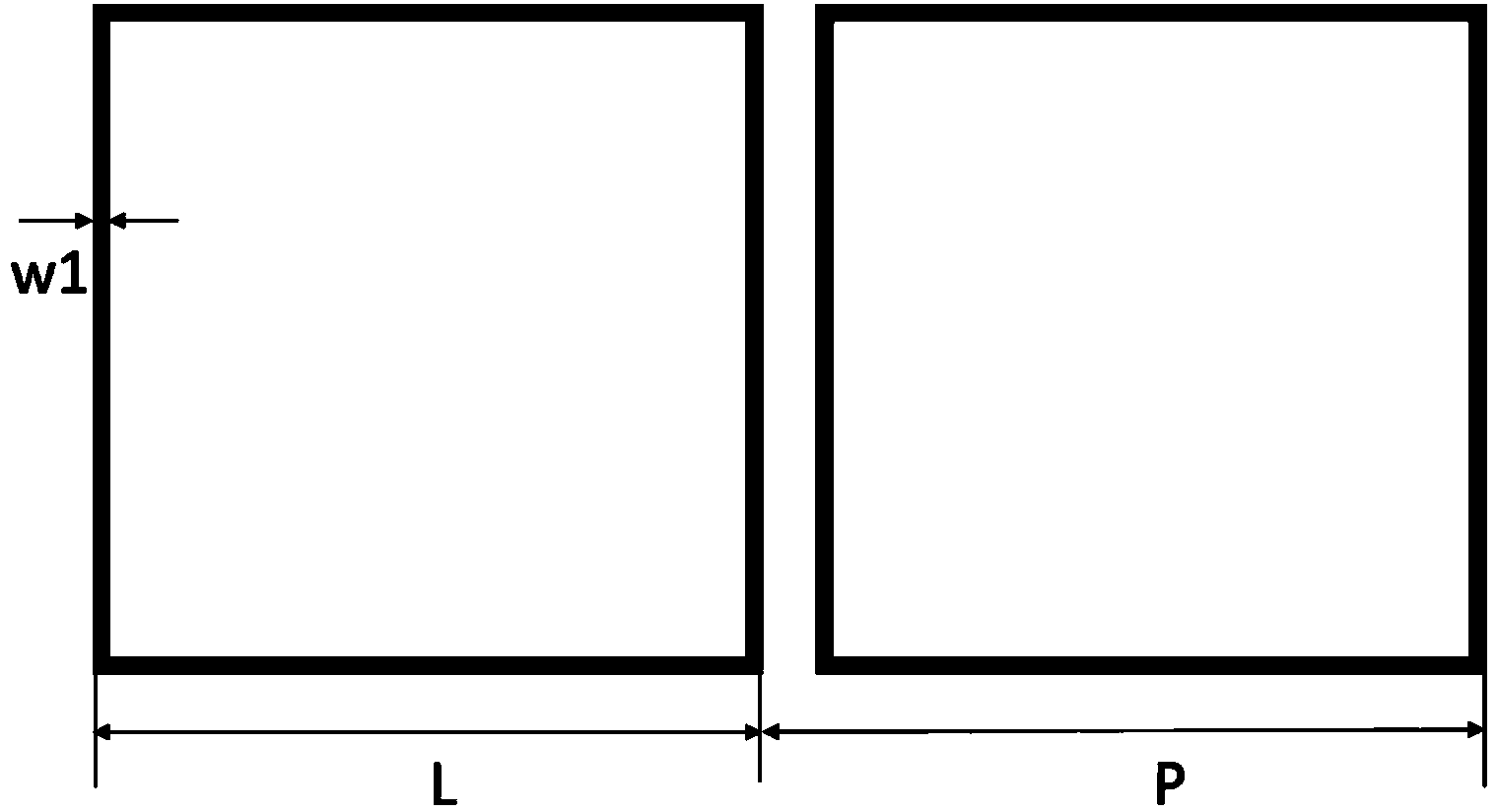
[0028] When P=4mm, L=3.8mm, d=0.8mm, w1=w2=30μm, f=300μm, N=5, h=200μm, each overall structural periodic unit has a square metal ring and 5×5 The metal grid line, the horizontal distance between the edge of the square ring and the outermost metal grid line is 300 μm. The material of the optical window dielectric layer is quartz glass (dielectric constant is about 4.3), and the metal of the metal ring periodic structure and the metal grid periodic structure is selected as gold (conductivity is 4×10 7 S / m), according to the constraints, we get as Figure 1~4 The schematic diagram of the periodic structure shown, according to the low duty cycle of the structure and the transmittance of quartz glass (>90%), the results show that the transmittance of the optical window of the narrow bandpass frequency selective surface of the present invention is greater than 85%.

[0029] Calculate the radar wave band-pass transmission characteristics of the obtained narrow-band-pass frequency se...

Embodiment 11

[0034] When the metal ring periodic structure in embodiment 1 is circular ring periodic structure 4, as Figure 5 As shown, the ring diameter 2R is 3.8 μm, the line width w3 is 20 μm, and other parameters are the same as in Example 1. The radar wave band-pass transmission characteristics of the obtained narrow-band-pass frequency selective surface are calculated, and the results are shown in Image 6 In curve b, the result is similar to the bandpass filtering effect of the square ring structure (peak transmittance -1.02dB at 11.12GHz).

Embodiment 12~13

[0036] When the thickness of the metal wires in the metal ring periodic structure and the metal grid periodic structure in Example 1 is 5 or 8 μm, the bandpass filtering effect shown by the narrowband and frequency selection is similar to that of Example 1.


PUM

PropertyMeasurementUnit
Thicknessaaaaaaaaaa
Thicknessaaaaaaaaaa
Line widthaaaaaaaaaa

Abstract

A narrow band pass frequency selective surface comprises a metal ring periodic structure, an optical window dielectric layer and a metal mesh periodic structure. The metal ring periodic structure and the metal mesh periodic structure are attached to the surface of the optical window dielectric layer or embedded in the optical window dielectric layer, the cycle of the metal ring periodic structure is P, and the cycle P of the metal ring periodic structure contains side lengths L of metal rings and the shortest distance g between the adjacent metal rings; the cycle of the metal mesh periodic structure is d, and P is an integral multiple of d. The narrow band pass frequency selective surface has the frequency selection characteristic of narrow band pass filtering in the 1-18 GHz radar frequency band while guaranteeing high permeability of visible/infrared windows, and has the advantages that pass band positions are flexible and adjustable, and polarization angles are insensitive and ultrathin. The narrow band pass frequency selective surface is suitable for wide frequency spectrum electromagnetic shielding and filtering in the field of telemetering, medical diagnosis, confidential communication, aerospace aviation and the like.

Description

technical field [0001] The present invention relates to electromagnetic shielding and filtering, in particular to a narrow bandpass frequency selective surface. technical background [0002] With the continuous development and progress of science and technology, the space electromagnetic environment is becoming more and more complex. There are serious electromagnetic interference problems in optical windows in the fields of telemetry and remote sensing, medical diagnosis, secure communication, aerospace equipment, etc., not only from cosmic rays, satellite communications, External electromagnetic wave signals such as TV broadcasts will interfere with the internal working devices of the system, and internal electromagnetic signals will also leak and affect the outside world. Due to the permeability of optical windows to electromagnetic waves, it will become one of the important factors for aircraft exposure in military applications. At the same time, with the continuous brea...

Claims


Application Information

Patent Timeline
IPC IPC(8): H01P1/20
Inventor 张龙白正元居永凤姜雄伟
Owner SHANGHAI INST OF OPTICS & FINE MECHANICS CHINESE ACAD OF SCI
Why Eureka
Try Eureka