Revolution conveying device

A technology of conveying device and conveying trough is applied in the field of fluid transmission, which can solve the problems of increased cost and inconvenient maintenance, and achieves the effects of reliable connection, prevention of leakage and simplification of system structure.

Inactive Publication Date: 2013-02-13
JIANGSU WEIHE MARINE EQUIP
View PDF7 Cites 3 Cited by
  • Summary
  • Abstract
  • Description
  • Claims
  • Application Information

AI Technical Summary

Problems solved by technology

Each hydraulic crane in the ship market is equipped with a separate hydraulic pump station, and the inside of the tower body is used as an oil tank, which will increase a lot of cost, and it is very inconvenient to maintain
Due to the current sluggish ship market, some shipowners share a hydraulic pump station with the anchor winch pump station and crane pump station or share a hydraulic pump station with two or more cranes on board in order to save costs; A technical problem arises: the base column does not move, and when the tower rotates, since the hydraulic hose or oil pipe steel pipe is rigid, there is no way to move relative to the base column and the tower body, so that the hydraulic oil cannot be controlled through the pipeline In the unit system, such as hoisting system, slewing system system, luffing system

Method used


Image

  • Revolution conveying device
  • Revolution conveying device
  • Revolution conveying device

Examples


Embodiment Construction

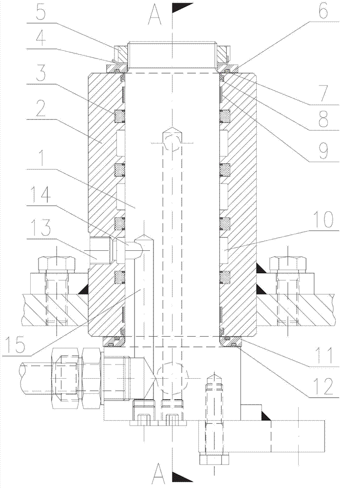
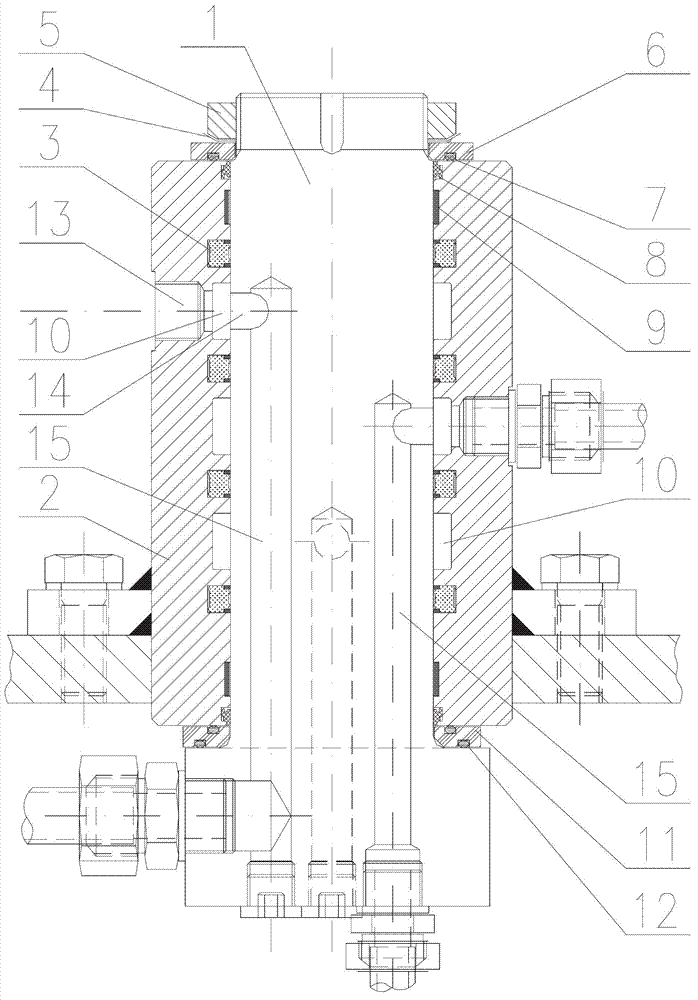
[0011] The present invention will be further described below in conjunction with the accompanying drawings.

[0012] like figure 1 , 2 As shown, the mandrel 1 and the slip ring body 2 of the rotary conveying device of the present invention are respectively fixed on the fixing mechanism of the mechanical equipment and the slewing mechanism rotating around the fixing piece through bolts and welding, etc., the lower end surface of the slip ring body 2 and the There is a lower copper washer 11 between the mandrel 1, and an annular groove 12 is processed on the upper and lower end surfaces of the lower copper washer 11 to store the sealing ring, so that the lower end surface of the slip ring body 2 and the mandrel 1 form an end face seal to prevent hydraulic oil from leaking. External leakage; the inner circumference of the slip ring body 2 is separated from the sealing groove, and the rotary seal 3 is embedded in the sealing groove, and there is an annular conveying groove 10 bet...


PUM


Abstract

The invention relates to a revolution conveying device and belongs to the technical field of fluid conveying devices. The revolution conveying device comprises a core shaft, slip ring members and rotation seals, the slip ring members are sleeved on the outer circumferential surface of a valve core, the rotation seals are located between the valve core and the slip ring members, conveying grooves are arranged between the valve core and the slip ring members and located between each two rotation seals, and connection holes which are communicated with the conveying grooves are opened on the slip ring members corresponding to the conveying grooves; and conveying channels are arranged in the core shaft, one ends of the conveying channels are connectedwith conveying channels to be connected, and the other ends of the conveying channels are communicated with the conveying grooves. Due to the conveying grooves, the conveying channels on the core shaft are communicated with the corresponding connection holes on the slip ring members in 360 degree directions. An external connection pipeline between a fixing mechanism and a revolution mechanism is omitted, phenomena of torsional damage and obstructed conveying of the connection pipeline in the process of rotation of the revolution mechanism are completely prevented, and advantages of system structure simplification and reliable connection are achieved.

Description

technical field [0001] The invention belongs to the technical field of fluid transmission between slewing equipment, in particular to a hydraulic oil transmission device for a hydraulic crane. Background technique [0002] Marine or engineering ships are generally equipped with hydraulic cranes and anchor winches. Each hydraulic crane in the ship market is equipped with a separate hydraulic pump station, and the inside of the tower body is used as an oil tank, which will increase a lot of cost and is very inconvenient to maintain. Due to the current sluggish ship market, some shipowners share a hydraulic pump station with the anchor winch pump station and crane pump station or share a hydraulic pump station with two or more cranes on board in order to save costs; A technical problem arises: the base column does not move, and when the tower rotates, since the hydraulic hose or oil pipe steel pipe is rigid, there is no way to move relative to the base column and the tower bod...

Claims


Application Information

Patent Timeline
Patent Type & Authority Applications(China)
IPC IPC(8): F16L39/06
Inventor 余小兵
Owner JIANGSU WEIHE MARINE EQUIP
Why Eureka
Try Eureka