Eureka AIR delivers breakthrough ideas for toughest innovation challenges, trusted by R&D personnel around the world.

A fresh air air handling unit with synchronous subcooling and superheating

An air handling unit and overheating technology, which is applied in the field of building environment and equipment engineering, can solve the problems of not considering the control of refrigerant superheat, affecting the stability and safety of the refrigeration system, and reducing the performance of fresh air air handling units. , to achieve the effect of guaranteeing performance, enhancing stability and reliability, and improving refrigeration energy efficiency ratio

Active Publication Date: 2015-10-21
NANJING NORMAL UNIVERSITY
View PDF4 Cites 0 Cited by
  • Summary
  • Abstract
  • Description
  • Claims
  • Application Information

AI Technical Summary

Problems solved by technology

At this time, it is difficult to ensure a certain degree of subcooling of the refrigerant, which is not conducive to the stable operation of the expansion valve.
[0009]In addition, it is worth noting that the superheat of the refrigerant at the compressor inlet often needs to be controlled at 5°C to 11°C: if the superheat is too low, the compressor is prone to wet compression , which affects the stability and safety of the refrigeration system; if the degree of superheat is too high, the exhaust temperature of the compressor is too high, the input power of the compressor increases, and the performance of the fresh air air handling unit decreases. At the same time, its stability and safety are also affected. less than guaranteed
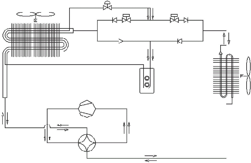
Invention patent CN101576297 B is a fresh air air handling unit with large supercooling degree, without considering the problem of refrigerant superheat degree control

Method used


Image

  • A fresh air air handling unit with synchronous subcooling and superheating
  • A fresh air air handling unit with synchronous subcooling and superheating
  • A fresh air air handling unit with synchronous subcooling and superheating

Examples


Embodiment 1

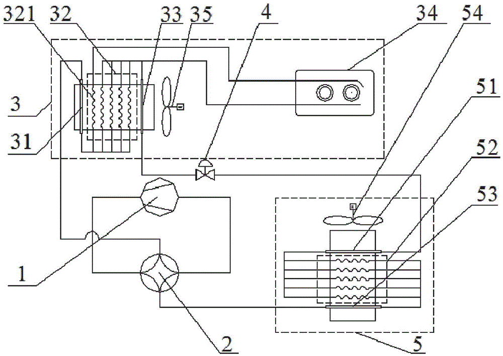
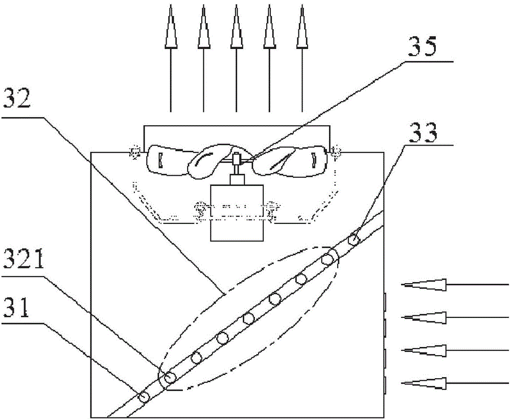
[0040] Embodiment 1 of the present invention is the first type of outdoor processing unit heat exchanger 3 and indoor air supply unit heat exchanger 5 . Both the fans of the heat exchanger 3 of the outdoor processing unit and the heat exchanger 5 of the indoor air supply unit are upward air outlets, and the distribution vector diagrams of their wind speeds conform to the upper triangle. When the structure of the heat exchanger is determined, this specific air supply mode has a one-to-one correspondence with the upper triangle distribution vector diagram of the wind speed. It can be seen from the upper triangular wind speed distribution vector diagram that the wind speed at the upper part of the heat exchanger is high, so when the external air sweeps across the upper branch of the heat exchanger, the effect of forced heat exchange with the refrigerant in the tube is good. The uppermost branch of the heat exchanger 5 of the device 3 and the indoor air supply unit is set as an ou...


PUM


Abstract

The invention discloses a full-fresh-air air handling unit capable of overcooling and overheating synchronously. The full-fresh-air air handling unit comprises a compressor, a four-way reversing valve, an outdoor handling unit heat exchanger, a bi-directional expansion valve and an indoor air supply unit heat exchanger. An air inlet end and an air outlet end of the compressor are connected with two opposite connectors on the four-way reversing valve respectively, a refrigeration inlet of the outdoor handling unit heat exchanger and a refrigeration outlet of the indoor air supply unit heat exchanger are connected with the other two opposite connectors on the four-way reversing valve respectively, and a refrigeration outlet of the outdoor handling unit heat exchanger is connected with a refrigeration inlet of the indoor air supply unit heat exchanger through the bi-bidirectional expansion valve. The full-fresh-air air handling unit effectively solves the problem of loss of obtained overcooling degree, improves the stability and reliability of working of the expansion valve, avoids wet compression of the compressor, can improve safety and reliability of the unit, and increases working energy efficiency ratio.

Description

technical field [0001] The invention relates to a fresh air handling unit, in particular to a fresh air handling unit with synchronous supercooling and overheating, belonging to the technical field of building environment and equipment engineering. Background technique [0002] The Fresh Air Handling Unit is a device that uses direct evaporative cooling or heat pump heating to deal with fresh air, and directly provides centralized processing of fresh air to confined spaces, rooms or areas through air ducts. It is widely used in pharmaceuticals, chemicals, Food, electronics, metallurgy and other fields. At present, the direct evaporative fresh air air handling unit is usually composed of a compressor, a four-way reversing valve, an outdoor processing unit heat exchanger, an expansion valve and an indoor air supply unit heat exchanger. Under this condition, the heat exchange generated by the phase change of the refrigerant with the external environment is used to improve the ...

Claims


Application Information

Patent Timeline
Patent Type & Authority Patents(China)
IPC IPC(8): F24F1/16F25B29/00F25B41/04F25B41/06
Inventor 张忠斌黄虎袁祎刘晓露张敬坤刘娜潘亚梅
Owner NANJING NORMAL UNIVERSITY
Why Eureka
Eureka Blog
Learn More