Portable magnetic metal fatigue detection method

A magnetic metal, fatigue detection technology, applied in the direction of material breakdown voltage, etc., can solve the problems of inability to weld and other defects diagnosis, provide a clear basis for repair, operator health threat, expensive and other problems, to facilitate monitoring and follow-up processing , The measurement process is simple and convenient, easy to mark and record the effect

Active Publication Date: 2013-02-13
CHONGQING JIAOTONG UNIVERSITY +1
View PDF3 Cites 2 Cited by
  • Summary
  • Abstract
  • Description
  • Claims
  • Application Information

AI Technical Summary

Problems solved by technology

Considering the actual situation, both X-ray flaw detection and gamma-ray flaw detection are radioactive element ray flaw detection, which not only need to use radioactive sources to emit rays, but also radioactive element ray flaw detection is extremely harmful to people, and careless operation will cause the operator to be injured by radiation. , pose a threat to the health of operators; the results of ultrasonic flaw detection are not intuitive, and cannot accurately determine the nature, quantity, size, shape, location, etc. of welding and other defects, and cannot provide a clear basis for the diagnosis and repair of welding and other defects
In addition, the existing various ray and ultrasonic flaw detection instruments also have the disadvantages of being heavy and expensive, and cannot conveniently and real-timely detect the entire railway line.

Method used


Image

  • Portable magnetic metal fatigue detection method
  • Portable magnetic metal fatigue detection method
  • Portable magnetic metal fatigue detection method

Examples


Embodiment Construction

[0034] The specific implementation manners of the present invention will be described in detail below in conjunction with the accompanying drawings.

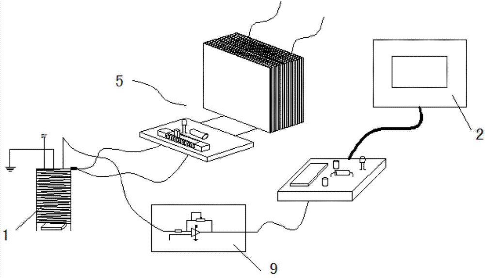
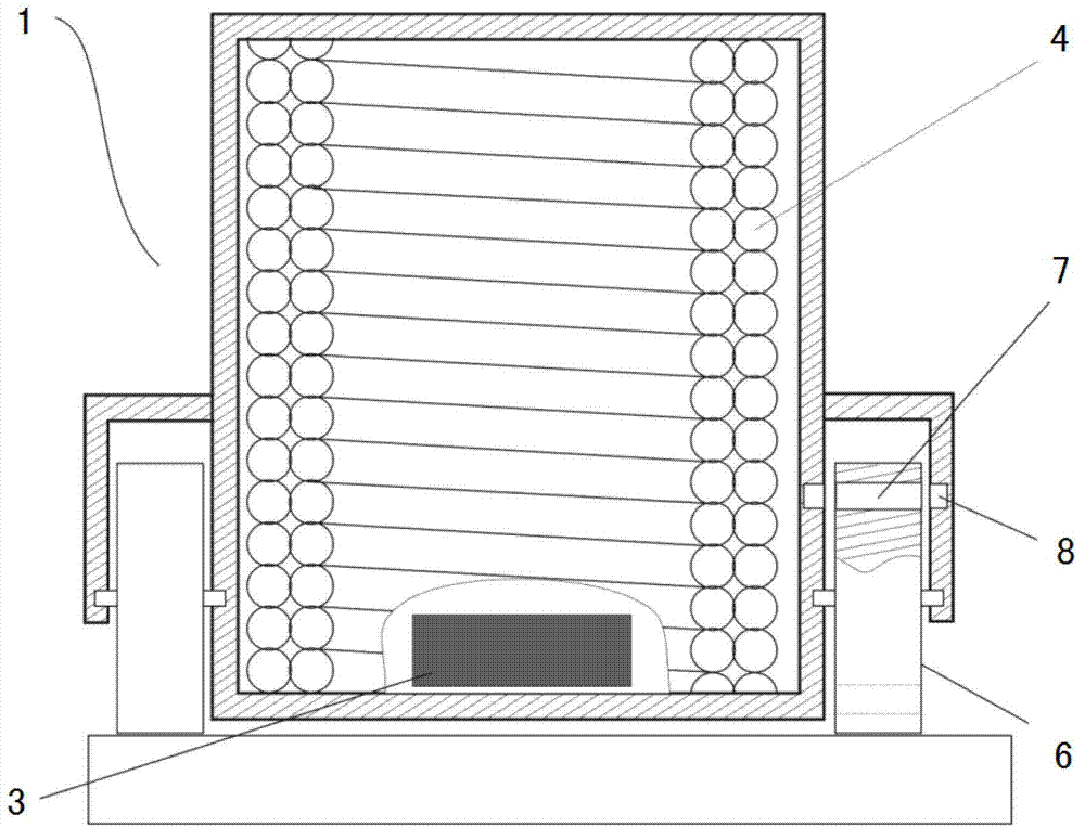
[0035] like figure 1 As shown, it is a structural schematic diagram of one of the portable magnetic metal fatigue detectors suitable for the portable magnetic metal fatigue detection method of the present invention. The portable magnetic metal fatigue detector comprises a probe 1, a data processing device connected to the probe 1 and a display 2 connected to the data processing device and used for displaying waveforms. The probe 1 includes a Hall sensor 3 for detecting the rate of change of a magnetic field and a stable The voltage and direct current power supply 5 is connected and used to generate the electromagnet coil 4 of the magnetic field. The Hall sensor 3 is installed at one end of the electromagnet coil 4 and is located on the top of the probe 1 .

[0036] In this portable magnetic metal fatigue detector, an electromag...


PUM

PropertyMeasurementUnit
thicknessaaaaaaaaaa

Abstract

The invention discloses a portable magnetic metal fatigue detection method. The method comprises the following steps of: 1, correction: placing a probe on the surface or the constant-height surface of the non-damage area of magnetic metal to be detected, adjusting the current I of an electromagnet coil, and correcting the output voltage of a Hall sensor; 2, detection: moving the probe along the surface of the magnetic metal to be detected or moving the probe along the constant-height surface of the surface of the magnetic metal to be detected, which is the same as the constant-height surface in the step 1, and by the relationship between the hall voltage UH and the magnetic conductivity of the magnetic metal to be detected, detecting the magnetic conductivity at each detecting position to obtain a micro r curve between the magnetic conductivity micro r and the detected position X or build a UH-X curve between the Hall voltage UH and the detected position; and 3, judgment: judging the position of an area where the micro-r-X curve or UH-X curve fluctuates wildly, which proves that the magnetic metal to be detected has fatigue damage at the position.

Description

technical field [0001] The invention belongs to the technical field of metal fatigue detection, in particular to a portable magnetic metal fatigue detection method for detecting magnetic metal fatigue damage. Background technique [0002] Since the 1980s and 1990s, steel structures have been widely used in domestic bridge construction, high-rise buildings, railway construction and other industries. As the proportion of steel in building materials increases year by year, the incidence of safety accidents caused by metal fatigue damage is also increasing year by year. All over the world, safety accidents caused by metal fatigue damage have caused very painful injuries to people. For example, in the accident on June 3, 1998, the high-speed train in Ezüd, Germany, the high-speed train derailed and hit the land bridge, resulting in 101 People died, and the cause of the accident was the fatigue damage of the train wheels during high-speed running. It was at that time that German...

Claims


Application Information

Patent Timeline
Patent Type & Authority Applications(China)
IPC IPC(8): G01N27/92
Inventor 周平陈皓张冠南梁红艮
Owner CHONGQING JIAOTONG UNIVERSITY
Why Eureka
Try Eureka