Multi-pass phase modulation device of high-power laser system

A phase modulation, laser system technology, applied in lasers, laser parts, optics, etc., can solve the problems of small phase modulator, increased optical pulse loss, energy drop, etc., and achieve the effect of improving spectral broadening ability

Active Publication Date: 2013-02-13
SHANGHAI INST OF OPTICS & FINE MECHANICS CHINESE ACAD OF SCI
View PDF3 Cites 8 Cited by
  • Summary
  • Abstract
  • Description
  • Claims
  • Application Information

AI Technical Summary

Problems solved by technology

[0005] However, the above-mentioned assumptions about multi-pass phase modulation proposed by Zhang Hujie et al. have the following disadvantages and deficiencies: (1), the device requires two electro-optical switches, and the cost is very high; (2), in the device, the optical pulse is M1 and M2 are multiple round-trip transmissions in the resonant cavity of the cavity mirror, and the beam will diverge with the increase of the transmission distance, while the light aperture of the phase modulator is small, and the light transmission of the bulk material phase modulator with a modulation frequency of 10 GHz The caliber is about 3×2mm (Jnoathan D.Zuegel and Douglas W.Jacobs-Perkins, Applied Optics, 43(9):1946(2004)), the final result of the beam divergence is that the light pulse is caused by the excessive beam size Can not completely pass through the phase modulator; (3), the transmission of the optical pulse in the cavity will produce a certain loss. decline, which ultimately limits the number of distances the light pulse travels in the cavity, and limits the spectral broadening capability of the device for the light pulse

Method used


Image

  • Multi-pass phase modulation device of high-power laser system
  • Multi-pass phase modulation device of high-power laser system
  • Multi-pass phase modulation device of high-power laser system

Examples


Embodiment Construction

[0033] The present invention will be further described below in conjunction with the embodiments and accompanying drawings, but the protection scope of the present invention should not be limited thereby.

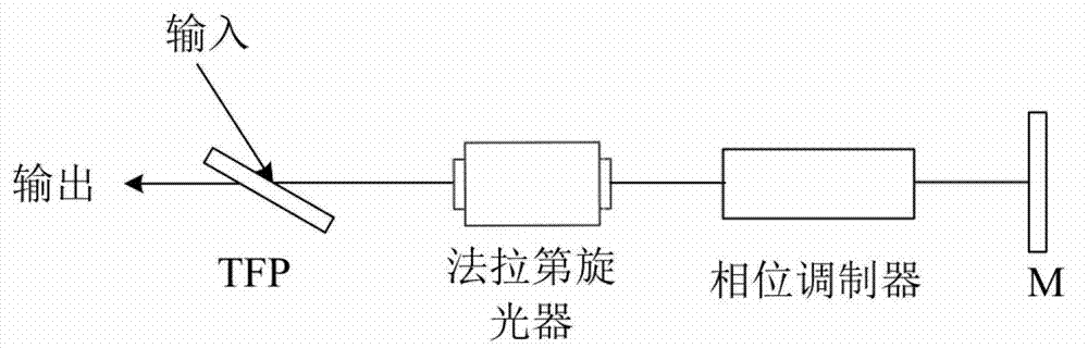
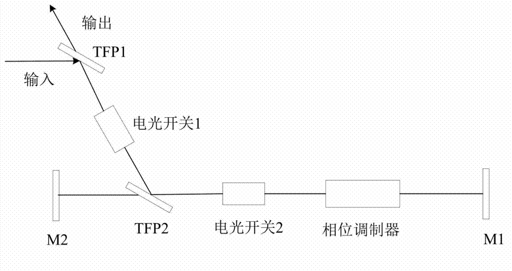
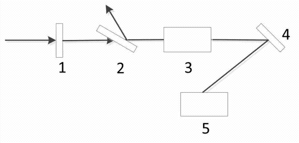
[0034] see first image 3 , Figure 4 and Figure 5 , image 3 is a structural schematic diagram of the multi-pass phase modulation device of the high-power laser system of the present invention, Figure 4 is a schematic structural view of the optical rotation unit of the present invention, Figure 5 It is a structural schematic diagram of the multi-pass phase modulation unit of the present invention. It can be seen from the figure that the multi-pass phase modulation device of the high-power laser system of the present invention consists of the first half-wave plate 1, the first thin-film polarizer 2, the optical rotation unit 3, and the first total reflection mirror placed in sequence along the beam traveling direction. 4 and a multi-pass phase modulation unit 5, the...


PUM


Abstract

The invention relates to a multi-pass phase modulation device of a high-power laser system. The multi-pass phase modulation device comprises a first half-wave plate, a first thin-film polarization film, a light rotation unit, a first totally-reflecting mirror and a multi-pass phase modulation unit which are sequentially arranged along an incident light beam advancing direction. An optical cavity structure is utilized to make an optical pulse repeatedly pass through a phase modulator, the phase modulation capability of the phase modulator on the optical pulse can be improved, and the multi-pass phase modulation device plays an important role in realizing uniform irradiation of a target surface of the high-power laser system.

Description

technical field [0001] The invention relates to a high-power laser system, in particular to a multi-pass phase modulation device for a high-power laser system, which plays an important role in realizing uniform irradiation of a target surface. Background technique [0002] In a high-power laser system, due to the needs of physical experiments, it is required that the final light intensity distribution irradiated on the target surface is a rectangular distribution with a flat top, steep edges and no side lobes. However, the optical pulse passes through multi-stage amplifiers in the high-power laser system, and when it is finally output, it will present certain intensity and phase distortion in space. On the other hand, even if the light pulse output from the high-power laser system is a uniform plane wave without intensity and phase distortion, when it irradiates the target surface through the focusing lens, affected by the diffraction effect, the far-field focal spot is appr...

Claims


Application Information

Patent Timeline
Patent Type & Authority Applications(China)
IPC IPC(8): G02B27/28G02B26/06H01S3/10
Inventor 张鹏李学春姜有恩黄阳彭宇杰徐鹏翔
Owner SHANGHAI INST OF OPTICS & FINE MECHANICS CHINESE ACAD OF SCI
Why Eureka
Try Eureka