
Method for energy optimization of distributed power generation and energy supply system

A distributed power generation and energy optimization technology, applied in system integration technology, information technology support systems, instruments, etc., can solve the problem of no heat load or cooling load analysis, few types of distributed power sources, and cannot fully and truly reflect the energy saving and reduction of distributed power sources. Efficiency and other issues

Inactive Publication Date: 2013-02-13
ELECTRIC POWER RESEARCH INSTITUTE, CHINA SOUTHERN POWER GRID CO LTD +1
View PDF0 Cites 27 Cited by
  • Summary
  • Abstract
  • Description
  • Claims
  • Application Information

AI Technical Summary

Problems solved by technology

Some scholars at home and abroad have carried out research on the energy-saving and emission-reduction benefits of introducing distributed power sources in the power distribution side, but there are few types of decentralized power sources to be optimized, and only the electrical load is simulated without corresponding heating or cooling loads. The analysis cannot fully and truly reflect the energy-saving and emission-reduction benefits of decentralized power sources

Method used


Image

  • Method for energy optimization of distributed power generation and energy supply system
  • Method for energy optimization of distributed power generation and energy supply system
  • Method for energy optimization of distributed power generation and energy supply system

Examples


Embodiment Construction

[0048] The present invention will be described in detail below with reference to the drawings and examples, but the embodiments of the present invention are not limited thereto.

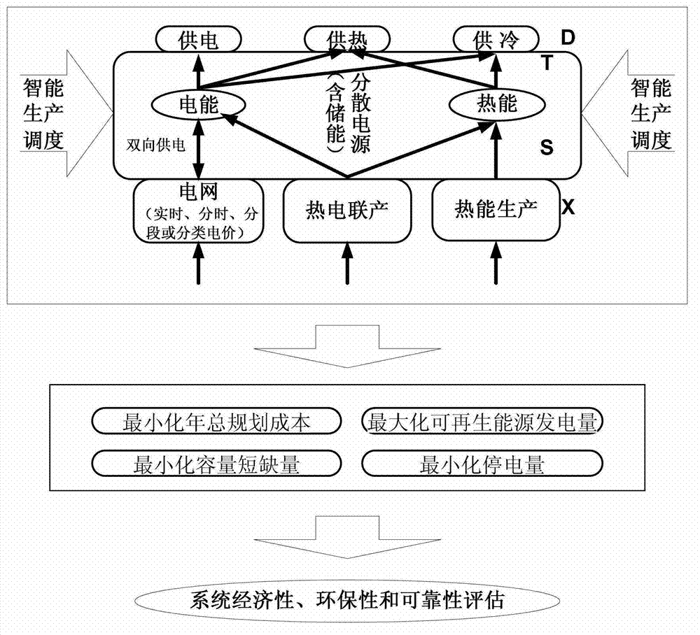
[0049] Such as figure 1 The energy optimization model of the distributed generation energy supply system is shown. The energy sources in the system include traditional centralized power plants (grids) and decentralized power sources, the latter including wind power generation WT, solar power generation PV, diesel generator DE, micro gas turbine GT and Battery energy storage BES, etc. D, T and S represent the energy demand layer, the transmission / transformation layer and the supply layer respectively, and X represents the external input of energy. Based on considerations of economy, environmental protection and reliability, a distributed generation supply system with four sub-objectives including minimizing annual total planning cost, maximizing renewable energy power generation, minimizing annual po...


PUM


Abstract

The invention provides a method for energy optimization of a distributed power generation and energy supply system, belonging to the technical field of electric power energy conservation. The method is mainly applied to evaluation of energy-saving and emission-reduction benefits of the distributed power generation and energy supply system when the distributed power generation and energy supply system is connected to an electric network. The method comprises the following steps of: firstly, establishing an energy optimization model of the distributed power generation and energy supply system with four sub-goals of minimizing the total annual planning cost, maximizing the generating capacity of renewable energy sources, minimizing the annual power failure quantity and minimizing the annual capacity shortage; secondly, defining goal optimization functions of the four sub-goals, unifying dimensions of the pollution discharge capacity, the power failure quantity and the capacity shortage of the system through gross penalty, and establishing a single-goal optimization function of the system by adopting a linear weighted sum method, wherein weighing coefficients are determined by adopting a dualistic contrast constant weight method; and finally, performing simulation and solving on the distributed power generation and energy supply system by adopting a heuristic global optimization algorithm to obtain values of the four optimization sub-goals. By the method, the multi-goal energy optimization of the distributed power generation and energy supply system is realized, and the aims of energy saving and emission reduction are achieved.

Description

technical field [0001] The invention belongs to the technical field of electric power conservation, and in particular relates to an energy optimization method for a distributed power generation energy supply system. Background technique [0002] While China Power has achieved great development and provided strong support for the development of my country's economy and other industries, it has also become an important contributor to China's environmental pollution. Therefore, energy saving and emission reduction is of great significance to the power industry. The rise and development of decentralized power supply provides a very promising energy-saving and emission-reduction technology for the power system. The access of the distributed generation energy supply system based on decentralized power sources is an important part of the future smart grid construction, and the realization of energy saving and emission reduction is one of the key goals of the smart grid operation. ...

Claims


Application Information

Patent Timeline
IPC IPC(8): G06Q10/04G06Q50/06
CPCY04S10/545Y02E40/76Y02E40/70Y04S10/50
Inventor 雷金勇甘德强段卫国辛焕海
Owner ELECTRIC POWER RESEARCH INSTITUTE, CHINA SOUTHERN POWER GRID CO LTD
Learn More