
Realization of control method and device for vacuum circuit breaker based on coil current

A vacuum circuit breaker and control method technology, applied in the direction of high-voltage air circuit breakers, circuits, high-voltage/high-current switches, etc., can solve problems such as limited number of measurements, limited application fields, and easy failures, and achieve convenient operation and stable measurement Good performance, weaken the effect of contact bouncing

Inactive Publication Date: 2013-02-13
BEIJING JIAOTONG UNIV
View PDF5 Cites 21 Cited by
  • Summary
  • Abstract
  • Description
  • Claims
  • Application Information

AI Technical Summary

Problems solved by technology

Although this method can control the stroke of the moving contact, because the internal measuring tap of the displacement sensor is in a moving state during the working process, it is prone to failure and the number of measurements is limited.
In addition, the displacement sensor usually needs to be directly connected with the moving contact rod, which is not easy to install, and it is easy to induce electrical failure
The closed-loop control method using the displacement sensor has limited its application field due to these disadvantages of the only sensor

Method used


Image

  • Realization of control method and device for vacuum circuit breaker based on coil current
  • Realization of control method and device for vacuum circuit breaker based on coil current
  • Realization of control method and device for vacuum circuit breaker based on coil current

Examples


example 1

[0083] This example takes a three-phase discrete control 12kV vacuum circuit breaker as an example, and specifically illustrates the setting method of the reference coil current curve of the control device suitable for the circuit breaker.

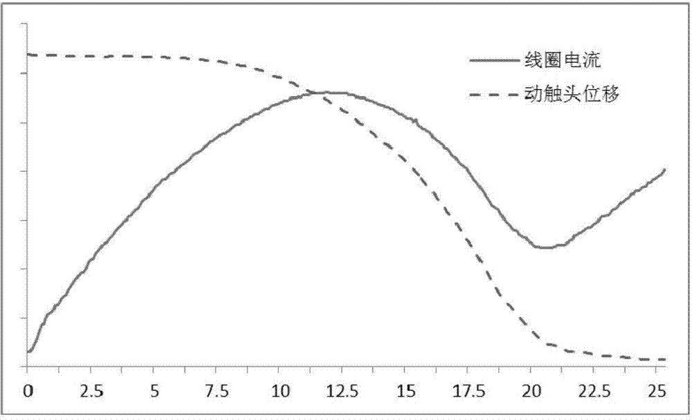
[0084] First, according to the parameters of the vacuum circuit breaker, the capacitance storage capacitors with capacitance values ​​of 2500μF and 4700μF are respectively selected for the measurement of the open loop current curve in the control device. Picture 9 In the case of an energy storage capacitor with an initial voltage of 210V and a capacitance value of 2500μF, the dynamic characteristic curve of the circuit breaker includes current, displacement and speed curves when opening and closing control is performed according to the open-loop control principle; Picture 10 It is the dynamic characteristic curve of the circuit breaker in the case of an energy storage capacitor with an initial voltage of 170V and a capacitance of 4700μF. For ...

example 2

[0087] This example is used to verify the driving coil current curve control method based on the present invention, in which a 4700μF energy storage capacitor is selected for experiment. Picture 11 with Picture 12 The comparison of the coil current curve output by the control device and the reference current current curve, and the comparison of the displacement curve and the displacement curve corresponding to the reference current curve, are given when the capacitance value of the energy storage capacitor is 4700μF and the initial voltage and voltage are respectively 200V.

example 3

[0089] This example is used to verify the driving coil current curve control method based on the present invention, in which a 47000μF energy storage capacitor is selected for experiment. Figure 13 with Figure 14 The comparison of the coil current curve output by the control device with a capacitance of 47000μF and a voltage of 180V with the reference current curve and the displacement curve corresponding to the reference current curve are given.


PUM


Abstract

The invention provides a control method and a control device for a permanent magnet vacuum circuit breaker. The control method comprises the following steps: measuring coil current of a permanent magnet mechanism; and acquiring a reference current curve for controlling in real time, as well as a hysteresis control algorithm unit. The control method is characterized in that any part is not required to be additionally arranged on a circuit breaker body; the current of a coil is measured in real time and is compared with reference current and an actual trigger signal of a power device is determined by a hysteresis control algorithm, so that the real-time closed loop control over the coil current is realized and further the switch-on-off time of the permanent magnet vacuum circuit breaker is kept consistent; and the realization of corresponding device is designed according to the method. Proved by actual experiments, the control method has the characteristics that the dispersibility of the switch-on-off time of the vacuum circuit breaker is effectively reduced and the dynamic error range of the switch-on-off of the vacuum circuit breaker is maintained at + / -0.3ms.

Description

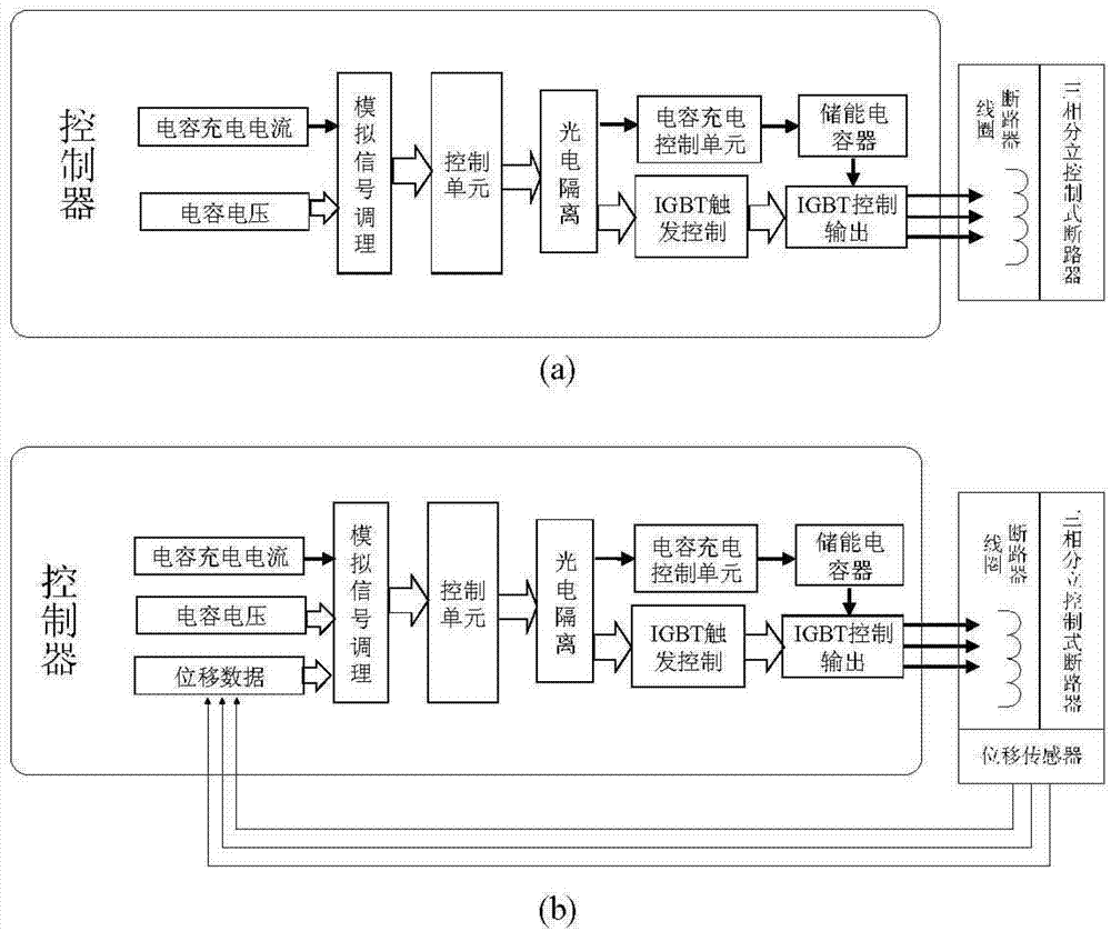
Technical field [0001] The invention relates to the technical field of control of a permanent magnet operating mechanism of a vacuum circuit breaker, in particular to a vacuum circuit breaker control device and a control method based on the coil current curve of the permanent magnet mechanism. Background technique [0002] Current circuit breaker control methods are mostly open-loop control methods, that is, the circuit breaker receives the opening and closing commands sent by the control device during the actual opening and closing operations, and triggers the corresponding IO completion commands, such as figure 1 Shown in A. This method cannot control the contact state of the circuit breaker. In the case of a higher operating voltage and the contact is in the open position to perform the opening operation and the contact is in the closing position to perform the closing operation, it is easy to be caused by the current passing through the coil. Too large causes the coil of the ...

Claims


Application Information

Patent Timeline
IPC IPC(8): H01H33/66H01H33/666
Inventor 吕锦柏王毅刘焱肖建涛
Owner BEIJING JIAOTONG UNIV
Learn More