Thyristor module
What is Al technical title?
Al technical title is built by PatSnap Al team. It summarizes the technical point description of the patent document.
A technology of thyristors and conductive blocks, which is applied in the field of power semiconductor module manufacturing, can solve the problems of pressing the shell, difficulty in realization, and many failures
Active Publication Date: 2015-04-08
JIANGSU APT SEMICONDUCTOR CO LTD
View PDF6 Cites 0 Cited by
Summary
Abstract
Description
Claims
Application Information
AI Technical Summary
This helps you quickly interpret patents by identifying the three key elements:
Problems solved by technology
Method used
Benefits of technology
Problems solved by technology
[0005] The main disadvantages of this current connection mode are: the high temperature line 9 and the copper foil area 51 of the DBC board (such as Figure 10 Shown) welding is point-to-surface welding, the process is difficult
Difficult to implement, many failures
In addition, the high-temperature wire 9 suspended in the air without fixing is easy to be pressed by the casing in subsequent operations, causing new failures
Method used
Image
Click on the blue label to locate the original text in one second.
Reading with bidirectional positioning of images and text.
Examples
Embodiment Construction
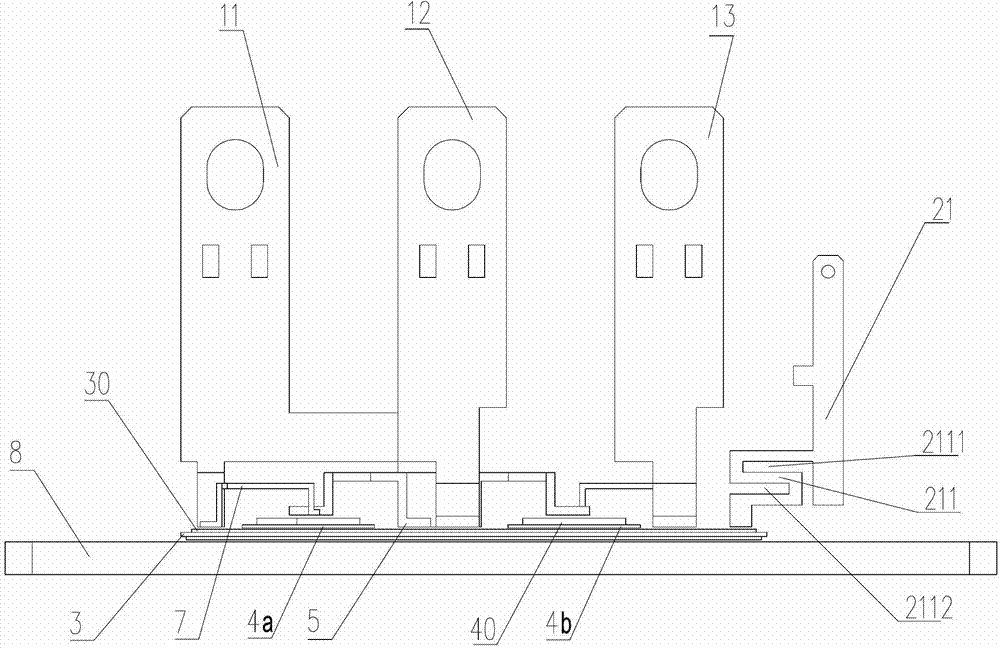
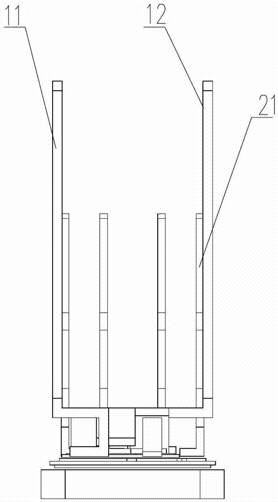
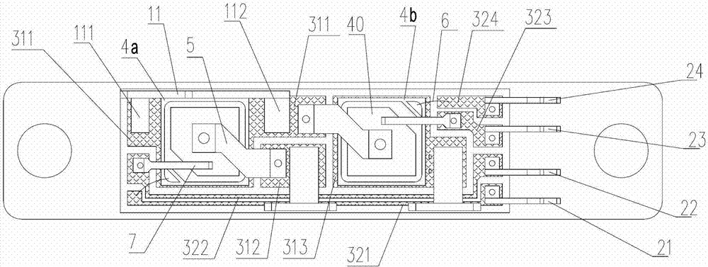
[0037] The present invention as Figure 1-6 As shown, it includes base plate, shell, substrate, chip one, chip two, electrode one, electrode two, electrode three, signal terminal Ga, signal terminal Ka, signal terminal Kb and signal terminal Gb; the fronts of the two chips are anodes A, the back is provided with a cathode K and a gate G; the top surface of the substrate is printed with mutually insulated conductive block area 1, conductive block area 2, conductive block area 3, conductive line area 1, conductive line area 2, conductive Line area three and conductive line area four;
[0038] The electrode 1, the anode A of the chip 1 and the cathode K of the chip 2 are connected to the conductive block area 1;
[0039] The electrode 2 and the cathode K of the chip 1 are connected to the conductive block area 2;
[0040] The electrode 3 and the anode A of the chip 2 are connected to the conductive block area 3;
[0041] The gate G of the chip 1 is connected to the conductive ...
PUM
Abstract
The invention discloses a thyristor module, belonging to the field of manufacturing of power semiconductor modules. The thyristor module adopts a new way to connect a chip and a signal end, therefore, the process and the material are simplified, and the product has connecting structure which is high in reliability and consistency, thereby remarkably optimizing the performance of the product. The thyristor module comprises a bottom plate, a housing, a substrate, a chip I, a chip II, an electrode I, an electrode II, an electrode III, a signal terminal Ga, a signal terminal Ka, a signal terminal Kb and a signal terminal Gb; the front surfaces of the two chips are provided with positive electrodes A, and the back surfaces are provided with negative electrodes K and gates G; and a conductive block zone I, a conductive block zone II, a conductive block zone III, a conductive wire zone I, a conductive wire zone II, a conductive wire zone III and a conductive wire zone IV which are mutually insulated are printed on the top surface of the substrate. According to the thyristor module, the consistency of the product is greatly improved, and the reliability is enhanced as well. Therefore, the raw materials and the process steps of the product are greatly simplified, the manufacturing yield is improved, the performance and the consistency are remarkably enhanced, and the reliability is improved.
Description
technical field [0001] The invention relates to a thyristor power module and its internal connection mode of signal terminals, belonging to the field of power semiconductor module manufacturing. Background technique [0002] The thyristor power module is a collection of several thyristor chips packaged together according to certain topological functions. Generally, in a power module, the bottom surfaces of these thyristor chips are soldered to the metal surface of the insulating substrate. The insulating substrate enables the bottom of the chip to be electrically connected, and also has good heat dissipation performance and electrical insulation relative to the heat dissipation bottom plate. The upper surface of the chip is metallized (usually silver material), and the electrical connection can be realized by soldering molybdenum sheets and metal connection bridges. These power components are fully covered with silicone in the module so that the components are adequately i...
Claims
Application Information
Patent Timeline
Application Date:The date an application was filed.
Publication Date:The date a patent or application was officially published.
First Publication Date:The earliest publication date of a patent with the same application number.
Issue Date:Publication date of the patent grant document.
PCT Entry Date:The Entry date of PCT National Phase.
Estimated Expiry Date:The statutory expiry date of a patent right according to the Patent Law, and it is the longest term of protection that the patent right can achieve without the termination of the patent right due to other reasons(Term extension factor has been taken into account ).
Invalid Date:Actual expiry date is based on effective date or publication date of legal transaction data of invalid patent.