Stable intervertebral fusion cage

An intervertebral fusion device, a stable technology, applied in medical science, tissue regeneration, prosthesis, etc., can solve the problem of multi-level porous material properties such as uneven distribution of strength, elastic modulus, stress, and failure to meet the functions of bionic bone restorations Requirements, pore size and uncontrollable connectivity, etc., to avoid excessive gap between elastic modulus and vertebral elastic modulus, improve early stability, and excellent bending resistance

Inactive Publication Date: 2017-07-14
CHONGQING RUNZE PHARM CO LTD
View PDF10 Cites 0 Cited by
  • Summary
  • Abstract
  • Description
  • Claims
  • Application Information

AI Technical Summary

Problems solved by technology

[0004] As a multi-level porous material for bionic artificial bone, the material itself needs to be uniform in application, that is, the pore size and distribution are uniform, so that the performance is uniform, but in fact, the existing multi-level porous materials cannot meet this requirement. The layout of the level holes is random, the size and connectivity of the pores are uncontrollable, the distribution of the pores is not uniform, and there are internal defects, which cannot meet the functional requirements as a bionic bone restoration.
For example, although some materials claim to have achieved high uniformity, their uniformity is still the uniformity at the large volume scale. The three-dimensional body of centimeters, measured its mass separately, and the difference in the degree of inhomogeneity is still very large, so the various properties of the porous material such as strength, elastic modulus, stress distribution, etc. are inhomogeneous, which seriously affects its function.

Method used


Image

  • Stable intervertebral fusion cage
  • Stable intervertebral fusion cage
  • Stable intervertebral fusion cage

Examples


Embodiment 1

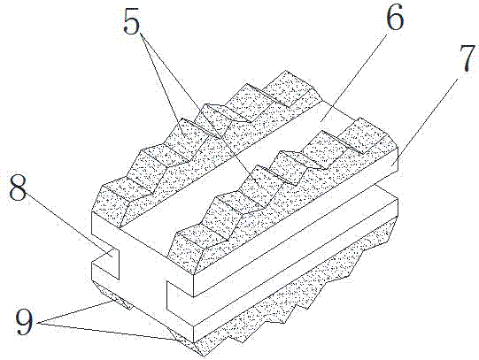
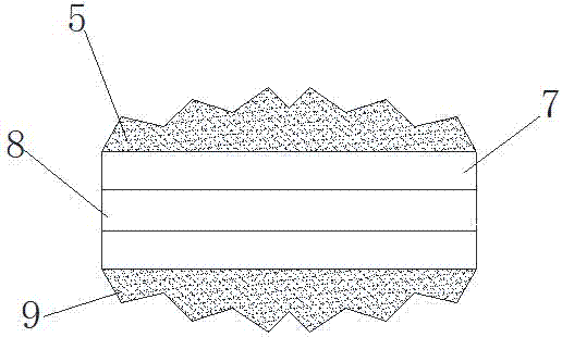
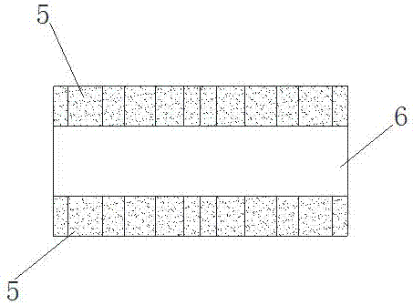
[0027] As attached to the manual Figure 1-4 Shown, a kind of stable intervertebral fusion device, it is divided into three layers of upper part, middle part 7 and lower part; The upper part is two strips 5 distributed along the direction from one end to the other end of the long side of middle part 7 at intervals, The two strips 5 are respectively located at the two edges of the upper end surface of the middle part 7, and between the two strips 5 is a long-in groove 6 through which both ends pass through; the two opposite long sides of the middle part 7 are respectively provided with a Along the direction from one end of the long side to the other end of the distribution of the two ends of the groove 8, and the two grooves 8 in the middle part 7 are symmetrical; the lower part is distributed along the direction from one end of the long side of the middle part 7 to the other end. The two strips 9 are located at the two edges of the lower end surface of the middle part 7 respec...

Embodiment 2

[0029] A stable intervertebral fusion device, its structure is the same as that of the stable intervertebral fusion device described in Example 1, the difference between the two is that the upper and lower parts of the stable intervertebral fusion device in this example are made of Made of multi-level porous metal materials; among them, multi-level porous metal materials such as Figure 5-7 As shown, in its multi-level porous metal material, 1 is the primary cavity, and 2 is the cavity wall of the primary cavity; the cavity wall 2 of the primary cavity 1 is composed of smaller secondary cavity 3 and surrounding secondary pores The cavity wall 4 of the cavity 3 is composed; combined with the enlarged view of the cavity wall 2 and the B-B cross-sectional view, the secondary cavity 3 is three-dimensionally connected; and so on, the cavity wall 4 of the secondary cavity 3 is formed by the 3 The smaller tertiary cavity and the cavity wall surrounding the tertiary cavity are formed,...

Embodiment 3

[0044] As attached to the manual Figure 1-4 Shown, a kind of stable intervertebral fusion device, it is divided into three layers of upper part, middle part 7 and lower part; The upper part is two strips 5 distributed along the direction from one end to the other end of the long side of middle part 7 at intervals, The two strips 5 are respectively located at the two edges of the upper end surface of the middle part 7, and between the two strips 5 is a long-in groove 6 through which both ends pass through; the two opposite long sides of the middle part 7 are respectively provided with a Along the direction from one end of the long side to the other end of the distribution of the two ends of the groove 8, and the two grooves 8 in the middle part 7 are symmetrical; the lower part is distributed along the direction from one end of the long side of the middle part 7 to the other end. The two strips 9 are located at the two edges of the lower end surface of the middle part 7 respec...


PUM

PropertyMeasurementUnit
pore sizeaaaaaaaaaa
pore sizeaaaaaaaaaa
particle diameteraaaaaaaaaa

Abstract

The invention relates to a stable intervertebral fusion cage comprising an upper portion, a middle portion (7), and a lower portion; the upper portion comprises two bar shaped bodies (5) arranged at an interval along the long side face direction of the middle portion (7), the two bar shaped bodies (5) are respectively located on two edges of the top end face of the middle portion (7), and a long inlet groove (6) is arranged between the two bar shaped bodies (5); the two opposite long side faces of the middle portion (7) are respectively provided with a groove (8) distributed in the long side face direction; the lower portion comprises two bar shaped bodies (9) arranged at an interval along the long side face direction of the middle portion (7), the two bar shaped bodies (9) are respectively located on two edges of the bottom end face of the middle portion (7), and a long inlet groove (10) is arranged between the two bar shaped bodies (9); the upper and lower portions are respectively made of porous metal material, and fixed with the middle portion (7)so as to form a whole body. The stable intervertebral fusion cage is simple in structure, light in weight, proper in elastic modulus, and can realize self-stability.

Description

technical field [0001] The invention relates to an intervertebral fixation device, in particular to a stable intervertebral fusion device. Background technique [0002] Clinically, implantation of an artificial intervertebral fusion device is often used to treat intervertebral disc herniation and intervertebral instability caused by spinal degeneration. Although this kind of operation can obtain relatively satisfactory curative effect, the effect of intervertebral fusion is greatly limited due to the following defects in the commonly used intervertebral fusion device: bulky product, strong foreign body sensation after implantation, complicated structural design, The structure is relatively cumbersome; the elastic modulus of the product is relatively high, and the gap between the elastic modulus of the product and the vertebral body is too large, which will cause stress shielding in the later stage, resulting in bone absorption, bone degeneration, and abnormal movement or deg...

Claims


Application Information

Patent Timeline
Patent Type & Authority Applications(China)
IPC IPC(8): A61F2/44A61L27/56A61L27/50A61L27/04
CPCA61F2/447A61F2002/30011A61F2310/00011A61L27/04A61L27/50A61L27/56A61L2430/38
Inventor 叶雷
Owner CHONGQING RUNZE PHARM CO LTD
Why Eureka
Try Eureka