
LDMOS (Laterally Diffused Metal Oxide Semiconductor) device and manufacturing method thereof

A technology of devices and well regions, which is applied in semiconductor/solid-state device manufacturing, semiconductor devices, electrical components, etc., can solve the problems of low maintenance voltage of LDMOS devices, unsatisfactory effects, and easy damage of devices, so as to improve ESD tolerance , Calorie reduction, and the effect of improving tolerance

Active Publication Date: 2013-02-13
CSMC TECH FAB2 CO LTD
View PDF6 Cites 2 Cited by
  • Summary
  • Abstract
  • Description
  • Claims
  • Application Information

AI Technical Summary

Problems solved by technology

[0005] However, for high-voltage devices, their own operating voltage is very high, and the maintenance voltage is very low. It is difficult to use the above method to increase the maintenance voltage of high-voltage devices to the level required to resist ESD. The increase is no longer effective
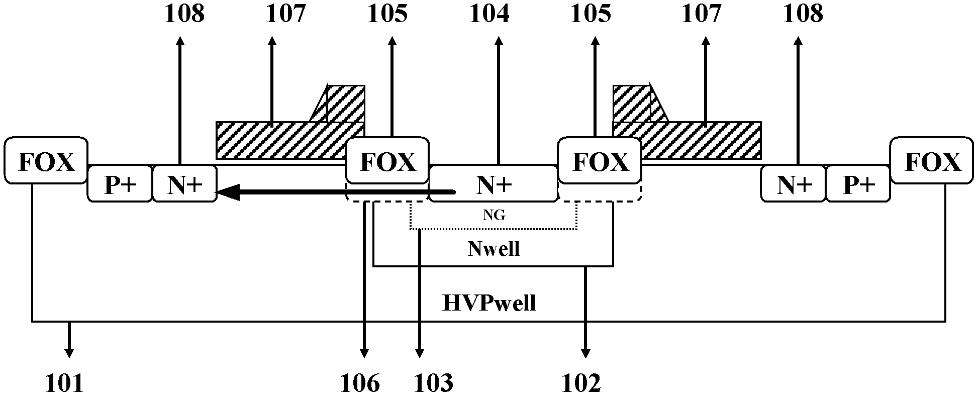
[0006] LDMOS (Lateral Double-diffuse MOS) devices are commonly used in existing ESD protection devices, especially in high-voltage processes, but the conditions of large current stress generated in the ESD process However, LDMOS devices are easily damaged, especially in high voltage processes
[0007] In the prior art, in order to improve the anti-ESD capability of the LDMOS device, the area of ​​the LDMOS device is usually increased, that is, in the multi-finger structure, the number of LDMOS devices is increased. However, due to the low sustain voltage of the LDMOS device itself, this The effect of this method is not very ideal

Method used


Image

  • LDMOS (Laterally Diffused Metal Oxide Semiconductor) device and manufacturing method thereof
  • LDMOS (Laterally Diffused Metal Oxide Semiconductor) device and manufacturing method thereof
  • LDMOS (Laterally Diffused Metal Oxide Semiconductor) device and manufacturing method thereof

Examples


Embodiment Construction

[0033] In order to make the above objects, features and advantages of the present invention more comprehensible, specific implementations of the present invention will be described in detail below in conjunction with the accompanying drawings.

[0034] In the following description, a lot of specific details are set forth in order to fully understand the present invention, but the present invention can also be implemented in other ways different from those described here, and those skilled in the art can do it without departing from the meaning of the present invention. By analogy, the present invention is therefore not limited to the specific examples disclosed below.

[0035] Secondly, the present invention is described in detail in combination with schematic diagrams. When describing the embodiments of the present invention in detail, for the convenience of explanation, the cross-sectional view showing the device structure will not be partially enlarged according to the gener...


PUM


Abstract

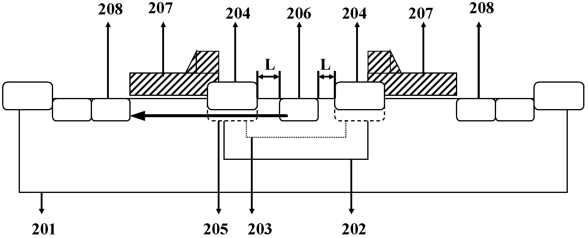
The embodiment of the invention discloses an LDMOS (Laterally Diffused Metal Oxide Semiconductor) device and a manufacturing method thereof. The LDMOS device comprises a substrate, wherein the substrate comprises a first trap region, a second trap region positioned in a surface of the first trap region, a doped region positioned in a surface of the second trap region, field oxide positioned on the periphery of the doped region and a drift region positioned at the lower part of the field oxide, wherein a drain region is positioned in a surface of the doped region, and a certain distance is arranged between an edge of the drain region and an edge of the drift region. According to the invention, since the distance between the edge of the drain region and the edge of the drift region is changed and increased, the resistance between the edge of the drain region and the edge of the drift region is increased, a current flow path between the edge of the drain region and the edge of the drift region is increased, the maintaining voltage of the device is improved, therefore when an ESD (Electrostatic Discharge) phenomenon occurs, current between the drain region and the drift region is not concentrated, the caloric power of the device is reduced so as to avoid burn-out of the device, and the withstanding capability of the LDMOS device to ESD is improved.

Description

technical field [0001] The invention relates to the technical field of semiconductor manufacturing, and more specifically, relates to an LDMOS device and a manufacturing method thereof. Background technique [0002] Electrostatic discharge (ESD) is a common natural phenomenon in daily life. The electrostatic discharge process can generate a large current in a short time. For example, the electrostatic discharge phenomenon (HBM for short) that occurs on the human body usually occurs within hundreds of nanoseconds. , the maximum current peak can reach several amperes, while in some other models, such as CDM (charged device model), MM (machine model), the electrostatic discharge occurs for a shorter time and generates a larger current, such a large current Passing through the integrated circuit in a short period of time will seriously exceed the maximum value that the circuit itself can withstand, resulting in serious physical damage to the integrated circuit, and in severe cas...

Claims


Application Information

Patent Timeline
Patent Type & Authority Applications(China)
IPC IPC(8): H01L29/78H01L21/336
CPCH01L29/66659H01L29/78H01L29/42368H01L29/0847H01L29/7835
Inventor 代萌林中瑀
Owner CSMC TECH FAB2 CO LTD
Learn More