Transmission method for physical downlink control channel
A physical downlink control and control channel technology, applied in wireless communication, multi-frequency code systems, electrical components, etc., can solve the problems of limited number of UEs, limited control channel transmission capacity, affecting MU-MIMO and CoMP performance gains, etc. The effect of increasing capacity
- Summary
- Abstract
- Description
- Claims
- Application Information
AI Technical Summary
Problems solved by technology
Method used
Image

Examples
Embodiment Construction
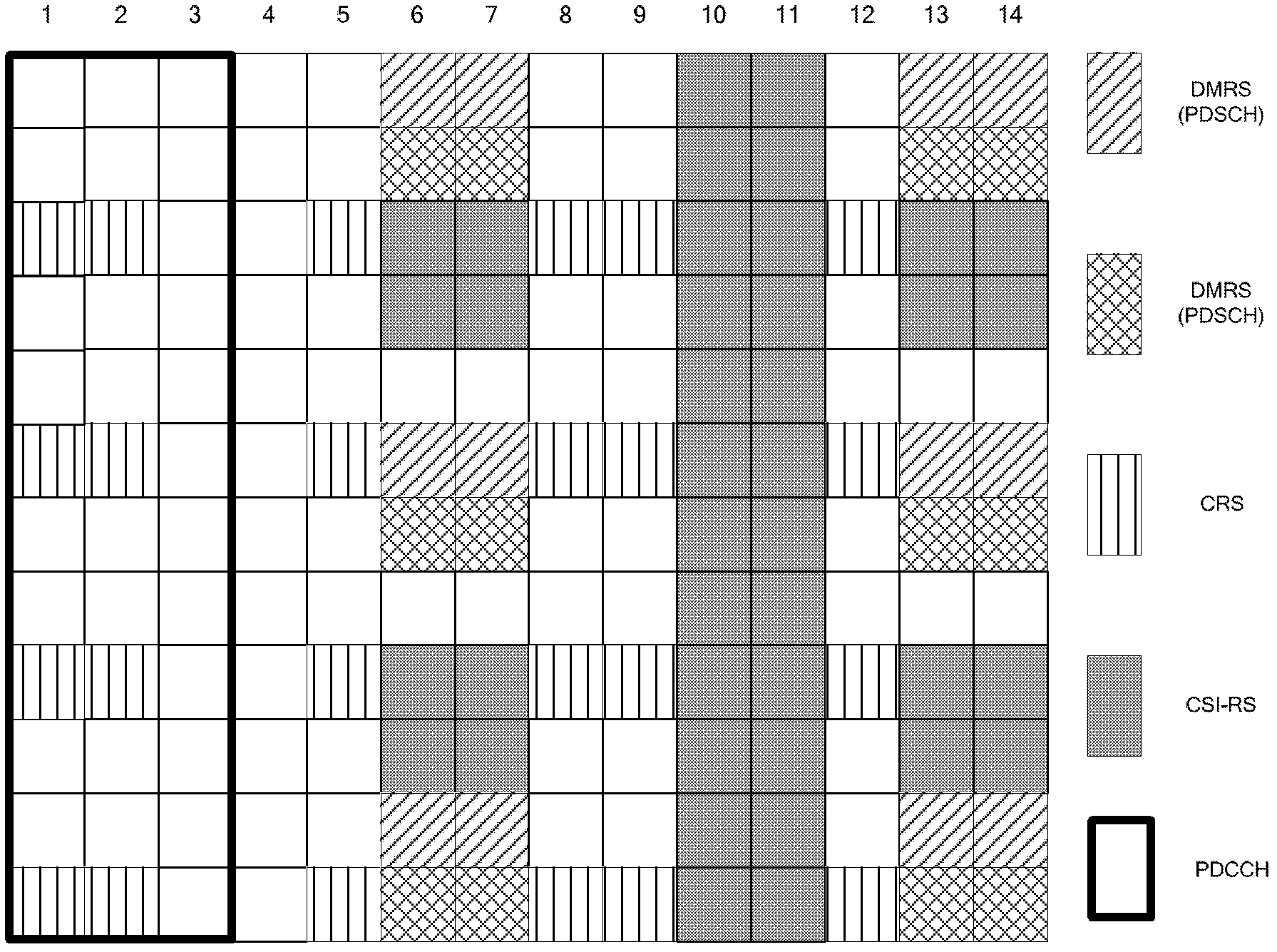
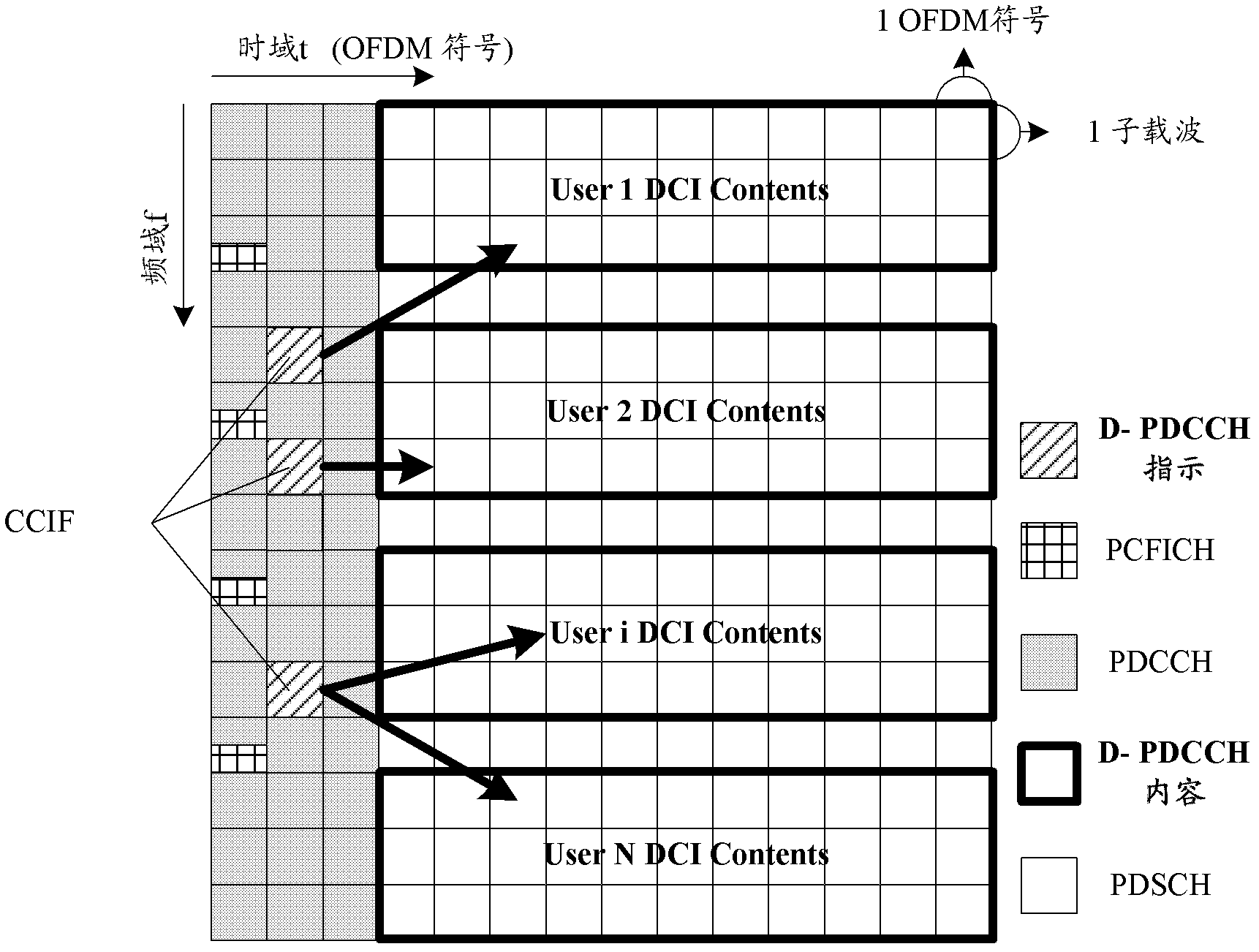
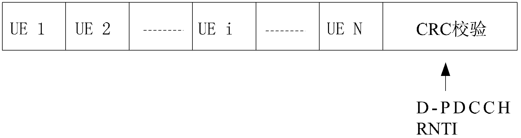
[0021] The core idea of the technical solution of the present invention is to design a "Control Channel Indication Field" (CCIF) for indicating the control information of the UE. The CCIF contains a small amount of indication information. / 9 / 10 UEs have the same number of CCEs to ensure backward compatibility; at the same time, the control channel indicator field is only placed in the UE-specific search space, which reduces the number of blind detections, reduces the complexity of the UE, and saves energy consumption. The physical downlink of the UE The content domain information of the control channel is carried on the original PDSCH, which significantly improves the capacity of the PDCCH carried by the subframe. The transmission strategy based on the demodulation of the demodulation reference signal DMRS (Demodulation Reference Signal) is used, that is, the scheme of introducing D-PDCCH (through DMRS based -RS demodulation PDCCH), compared with the PDCCH scheme based on CRS...
PUM
 Abstract
Description
Claims
Application Information
PatSnap Eureka turns technology decisions into work you can execute. Powered by our Innovation Knowledge Graph, it runs expert workflows across engineering, life sciences, materials and intellectual property. Get your review-ready output in minutes.


