Eureka AIR delivers breakthrough ideas for toughest innovation challenges, trusted by R&D personnel around the world.

Device for estimating amount of combustion product generation in internal combustion engine, device for estimating amount of deposit detachment, device for estimating amount of deposit accumulation, and device for controlling fuel injection

A technology of combustion products and fuel injection, which is applied to fuel injection devices, special fuel injection devices, engine control, etc., and can solve the problems of inability to inject fuel and the decline of exhaust characteristics of internal combustion engine output characteristics.

Active Publication Date: 2013-02-13
TOYOTA JIDOSHA KK
View PDF8 Cites 0 Cited by
  • Summary
  • Abstract
  • Description
  • Claims
  • Application Information

AI Technical Summary

Problems solved by technology

Moreover, when the combustion products are deposited on the wall surface of the injection hole in this way, there may be cases where the fuel injection valve cannot be injected with a command to inject a desired amount of fuel from the fuel injection valve. The injection valve injects the desired amount of fuel
Furthermore, when the expected amount of fuel cannot be injected from the fuel injection valve, the output characteristics and exhaust characteristics of the internal combustion engine may sometimes deteriorate.

Method used


Image

  • Device for estimating amount of combustion product generation in internal combustion engine, device for estimating amount of deposit detachment, device for estimating amount of deposit accumulation, and device for controlling fuel injection
  • Device for estimating amount of combustion product generation in internal combustion engine, device for estimating amount of deposit detachment, device for estimating amount of deposit accumulation, and device for controlling fuel injection
  • Device for estimating amount of combustion product generation in internal combustion engine, device for estimating amount of deposit detachment, device for estimating amount of deposit accumulation, and device for controlling fuel injection

Examples


Embodiment Construction

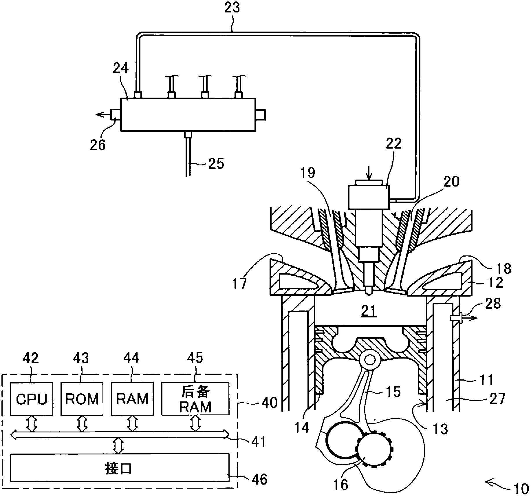
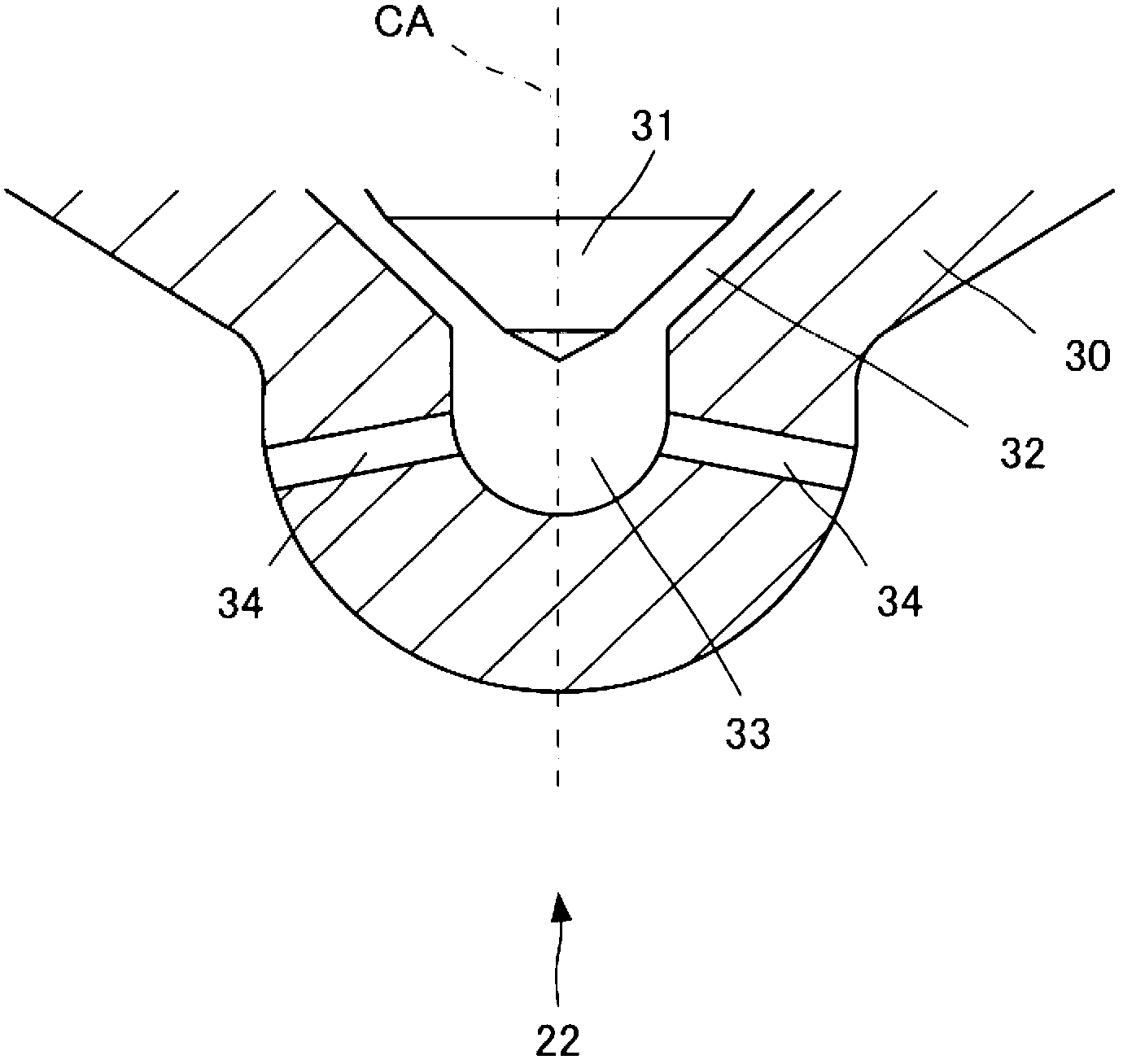
[0042] Hereinafter, embodiments of the present invention will be described with reference to the drawings. First, the structure of an internal combustion engine to which the present invention is applied will be described. The internal combustion engine such as figure 1 shown. exist figure 1 10 is the main body of the internal combustion engine, 11 is the cylinder block, and 12 is the cylinder head. A cylinder bore 13 is formed in the cylinder block 11 . A piston 14 is arranged inside the cylinder bore 13 . Piston 14 is connected to crankshaft 16 via connecting rod 15 . On the other hand, an intake port 17 and an exhaust port 18 are formed in the cylinder head 12 . Furthermore, an intake valve 19 for opening and closing the intake port 17 and an exhaust valve 20 for opening and closing the exhaust port 18 are arranged on the cylinder head 12 . In addition, the combustion chamber 21 is formed by the upper wall surface of the piston 14 , the inner peripheral wall surface o...


PUM


Abstract

The present invention pertains to a device that is for estimating the amount of deposit detachment and that estimates the amount of exit deposit detachment and the amount of entrance deposit detachment in an internal combustion engine (10) provided with a fuel injection valve (22) by calculating the amount of exit deposit detachment, which is the amount of combustion products that detach from among the combustion products accumulated at an injection hole exit region, and the amount of entrance deposit detachment, which is the amount of combustion products that detach from among the combustion products accumulated at an injection hole entrance region. In the present invention, the amount of exit deposit detachment is calculated on the basis of the amount of exit deposit accumulation, which is the amount of combustion products accumulated at the injection hole exit region, and the amount of entrance deposit detachment is calculated on the basis of the amount of entrance deposit accumulation, which is the amount of combustion products accumulated at the injection hole entrance region.

Description

technical field [0001] The present invention relates to a combustion product generation amount estimating device, a deposit stripping amount estimating device, a deposit accumulation amount estimating device, and a fuel injection control device for an internal combustion engine. Background technique [0002] There is known an internal combustion engine in which a fuel injection valve is arranged so that fuel is directly injected into a combustion chamber. In addition, it is also known that, in such an internal combustion engine, combustion products (ie, substances generated in connection with the combustion of fuel) are produced and that the combustion products accumulate in the injection hole area (ie, produced by the fuel injection valve The area inside the fuel injection hole, the area outside the fuel injection hole and the area near the entrance of the fuel injection hole, and the area outside the fuel injection hole and the area near the exit of the fuel injection hole...

Claims


Application Information

Patent Timeline
IPC IPC(8): F02M61/18
CPCF02D41/40F02M2200/06Y02T10/44F02M65/00F02M61/1806F02D41/221Y02T10/40
Inventor 池本雅里
Owner TOYOTA JIDOSHA KK
Why Eureka
Eureka Blog
Learn More