Moving device of pull head

A technology of moving devices and sliders, applied in the direction of sliding fastener components, applications, fasteners, etc., can solve the problems of high price and complicated structure, and achieve the effect of cheap price and simplified structure

Active Publication Date: 2015-04-29
YKK CORP
View PDF5 Cites 0 Cited by
  • Summary
  • Abstract
  • Description
  • Claims
  • Application Information

AI Technical Summary

Problems solved by technology

Therefore, there is a problem that the structure of the device is complicated and expensive

Method used


Image

  • Moving device of pull head
  • Moving device of pull head
  • Moving device of pull head

Examples


Embodiment Construction

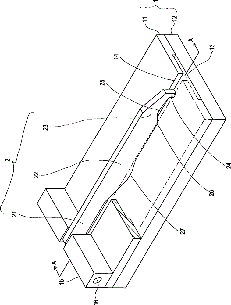
[0098] Hereinafter, embodiments of the slider moving device of the present invention will be described in detail with reference to the drawings. Hereinafter, unless otherwise specified, the "upstream side" means the upstream side in the conveying direction of the fastener chain, and the "downstream side" means the downstream side in the conveying direction of the fastener chain.

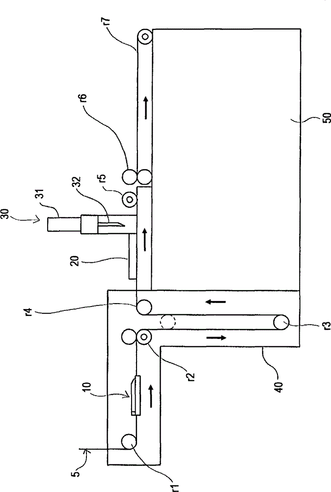
[0099] figure 1 Is a perspective view of the slider moving device 10, figure 2 It is a schematic front view showing an example of a zipper manufacturing device using the slider moving device 10.

[0100] Such as figure 2 As shown, in the slide fastener manufacturing apparatus, as indicated by the arrow, the long slide fastener chain is conveyed from the left side to the right side in the figure. In this manufacturing device, a guide roller r1, a slider moving device 10, a driving roller r2, a floating roller r3, a guide roller r4, a chain positioning unit 20, a cutting device 30, a driving roller r5, a...


PUM


Abstract

The invention provides a moving device of a pull head. Only a part is used for locking the pull head and a special drive source is not required, so that the structure is simple and the cost is low. The device comprises a body (10), an arm (2) and a spring, wherein the arm (2) can be supported in a rotary mode relative to the body (1), the spring can push and press the arm (2), the body is provided with a channel (13) through which a long zip of a zip can move, the arm is provided a base (21) which can be supported on the body in a rotary mode, a front end portion (23) which is arranged on the opposite side of the base and a middle portion (22) which is arranged between the base (21) and the front end portion (23), the front end portion is provided with a first projection (24), and the middle portion is provided with a second projection (27). When the arm is pushed and pressed by the spring and moves to a position which is close to the channel, the pull head (4) is hooked by the first projection, when a lower stopper abuts against the second projection, the second projection is pushed upwards by the lower stopper, the arm resists the press of the spring and moves to a position which is far away from the channel, and the first projection is unhooked with the pull head.

Description

Technical field [0001] The present invention relates to a slider moving device, in particular to a slider moving device for moving a slider mounted on a long zipper chain from a position away from the top stop to a position close to the top stop. Background technique [0002] In the manufacturing process of the zipper, the long zipper chain with the zipper element and the slider attached is cut to a predetermined length to obtain Picture 12 Zipper per unit length shown. Then, the quality of the zipper needs to be checked. [0003] The inspection items include, for example, whether there is a top stop, whether the top stop is firmly installed, whether there is a pull tab on the slider, whether the zipper element can pass through the inside of the slider correctly, whether there is a bottom stop, or a bottom stop. Whether the stop is firmly installed, etc. [0004] The inspection can be performed by equipment such as an image inspection unit, but due to the high price, the image insp...

Claims


Application Information

Patent Timeline
Patent Type & Authority Patents(China)
IPC IPC(8): A44B19/42A44B19/26
Inventor 上田俊一
Owner YKK CORP
Why Eureka
Try Eureka