Cutting knife

A technology of cutting knives and blades, which is applied in metal processing and other directions, can solve the problems of inconvenient processing, inconvenience, trouble, etc., and achieve the effect of convenient replacement

Active Publication Date: 2013-02-20
SHANGHAI KUNJEK HANDTOOLS & HARDWARE
View PDF9 Cites 0 Cited by
  • Summary
  • Abstract
  • Description
  • Claims
  • Application Information

AI Technical Summary

Problems solved by technology

[0004] Chinese patent application No. 03223149.0 discloses a combined cutting knife, which is characterized in that an upper cover and a locking plate are arranged on the knife seat, and the blade can be fastened by using both at the same time. This structure is too complicated, and the blade needs to be replaced. It is very troublesome to remove the upper cover and the locking plate at the same time
[0005] The Chinese patent application number is 200420102117.2, which discloses "a cutting knife", which uses locking screws to fix the blade. When replacing the blade, it is necessary to use a tool to unscrew the screw, which is relatively inconvenient.
Chinese patent application No. 200820153000.5 discloses a "two-way locking cutting knife", which realizes two-way shrinkage through a locking mechanism composed of a knife head locking plate, a front locking spring and a rear locking spring. Its structure is complex and inconvenient to process.

Method used


Image

  • Cutting knife
  • Cutting knife
  • Cutting knife

Examples


Embodiment 1

[0051] A cutting knife includes a knife head and a knife handle.

[0052] In this embodiment, the knife head and the knife handle are pivotally connected. During specific implementation, the knife head can also be telescopically connected to the knife handle, which is not limited in this embodiment.

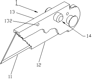
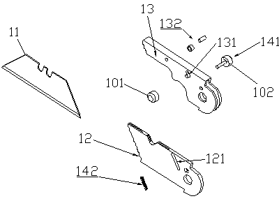
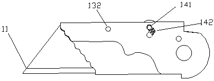
[0053] In this example, if figure 1 , the cutter head 1 includes a blade holder 12 for loading a blade 11, a base frame 13, and a first locking / unlocking device 14 for locking / unlocking the blade 11; Even; the first locking / unlocking device 14 is disposed between the blade seat 12 and the base frame 13 .

[0054] like figure 2 , the first locking / unlocking device 14 includes a toggle button 141 and a first elastic element. In this embodiment, the toggle knob 141 includes a first assembly 101 and a second assembly 102 ; the first elastic element is a compression spring 142 . During specific implementation, the types of the dial knob and the first elastic element can also ha...

Embodiment 2

[0063] The difference between this embodiment and Embodiment 1 is that the tool handle 2 includes a second locking / unlocking device 21 for locking / unlocking the tool head. For details, see Figure 5 , Image 6 and Figure 7 .

[0064] The second locking / unlocking device 21 includes a push button 211, a second elastic element 212 and a skeleton structure 22. In this embodiment, the skeleton structure 22 includes an upper skeleton 201 and a lower skeleton 202, and the push button 211 is symmetrical on both sides. Protrusions are provided, and the upper frame 201 and the lower frame 202 are symmetrically provided with limiting through holes 221 and 222 for accommodating the protrusions. In this embodiment, the second elastic element is two torsion springs 212, one end of each torsion spring is connected to the end of the push button 211, and the other end is connected to the skeleton structure, and the two torsion springs are arranged symmetrically. During specific implementat...


PUM


Abstract

The invention discloses a cutting knife which comprises a knife head portion and a knife handle portion. The knife head portion comprises a blade seat for loading blades, a base support and a first locking / unlocking device for locking / unlocking the blades. The blade seat is arranged in the base support to be pivoted with the base support, the first locking / unlocking device is arranged on the blade seat, the blade seat is fixed in the base support in a locking state, and the front end of the blade seat breaks away from the base support downwards in an unlocking state. The knife head portion is pivoted with the knife handle portion, the knife handle portion comprises a second locking / unlocking device for locking / unlocking the knife head portion, at least one boss is arranged on the blade seat, the second locking / unlocking device is clamped in the boss in a locking state, and the second locking / unlocking device breaks away from the boss in an unlocking state. The cutting knife can conveniently change the blades, enables the blades to be rigidly fixed during using and knife collection and removes potential safety hazards.

Description

technical field [0001] The invention relates to a cutting knife. [0002] Background technique [0003] Cutter is a more commonly used cutting tool, generally used for cutting paper, cloth, plastic and other materials. Generally, the cutting knife with replaceable blades is fixed by screws, but its disadvantage is that it is inconvenient to replace the blades. [0004] Chinese patent application No. 03223149.0 discloses a combined cutting knife, which is characterized in that an upper cover and a locking plate are arranged on the knife seat, and the blade can be fastened by using both at the same time. This structure is too complicated, and the blade needs to be replaced. It is very troublesome to remove the upper cover and the locking plate at the same time. [0005] Chinese patent application number is that the patent of 200420102117.2 discloses " a kind of cutter ", adopts lock piece screw to fix blade, needs to adopt tool to unscrew screw when it changes blade, co...

Claims


Application Information

Patent Timeline
IPC IPC(8): B26B5/00
Inventor 宋卫军
Owner SHANGHAI KUNJEK HANDTOOLS & HARDWARE
Why Eureka
Try Eureka