
Elastic buffer

An elastic buffering and buffering technology, applied in the field of rubber buffers, can solve the problems of complex elastic buffer structure, poor stop elastic performance, single function, etc., and achieve the effect of simple and reasonable structure, good buffering effect, and optimized structure.

Active Publication Date: 2013-02-27
ZHUZHOU TIMES RUIWEI ANTI VIBERATION EQUIP LTD
View PDF6 Cites 12 Cited by
  • Summary
  • Abstract
  • Description
  • Claims
  • Application Information

AI Technical Summary

Problems solved by technology

[0004] Aiming at the disadvantages of the existing elastic buffer of the suspension steel spring mechanism such as complex structure, single function, poor stop elastic performance, and inconvenient installation, the present invention provides a multifunctional elastic buffer with simple and reliable structure. The elastic buffer has three Functions: 1) The elastic buffer has a linear small stiffness characteristic with a large stroke, which can assist the steel spring to achieve a series of stiffness and play a role in damping vibration; 2) The elastic buffer has a characteristic of a sharp increase in stiffness when it is deformed, making the vehicle When the displacement of the primary suspension steel spring is large, the steel spring can be well protected; 3) The elastic buffer has a hard stop function, so that the vehicle can limit the maximum displacement of the primary suspension steel spring of the vehicle under special circumstances, and play a role The role of protecting the vehicle

Method used


Image

  • Elastic buffer
  • Elastic buffer

Examples


Embodiment 1

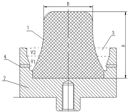
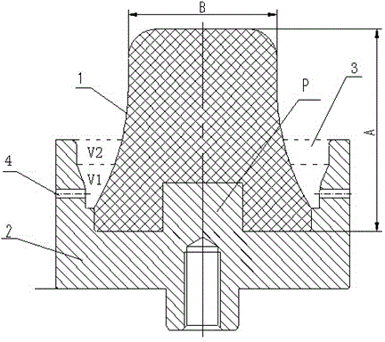
[0033] like figure 1As shown, a multi-functional elastic buffer includes a rubber body 1 and a metal base 2, the rubber body 1 is a conical structure, the ratio of its height A to the top diameter B is 1.0, and the bottom diameter C to the top diameter B The ratio range is 1.3, the top surface of the metal base 3 is provided with a rounded table-shaped counterbore 3, the bottom surface of the rubber body 1 is vulcanized at the bottom of the counterbore 3, the gap between the counterbore 3 and the rubber body 1 A space gap with a V-shaped axial section is formed between them, and the bottom end of the metal base 3 is connected to the steel spring system; the V-shaped space gap is organized by two parts, one is the V-shaped bottom space gap V1, and the volume ratio of VI and V2 is according to The rigidity requirement of the vehicle bogie for the buffer is designed to be 2:1. The side formed by the metal base in V1 is designed to be in the shape of a conical surface connected to...

Embodiment 2

[0035] A multifunctional elastic buffer, including a rubber body 1 and a metal base 2, the rubber body 1 is a conical structure, the ratio of its height A to the top diameter B is 1.6, and the ratio range of the top diameter B to the bottom diameter is 1.5 , the top surface of the metal base 3 is provided with a rounded table-shaped counterbore 3, the bottom surface of the rubber body 1 is vulcanized on the bottom of the counterbore 3, and a shaft is formed between the counterbore 3 and the rubber body 1. A V-shaped space gap is formed in the cross-section, and the bottom end of the metal base 3 is connected to the steel spring system; the V-shaped space gap is organized by two parts, one is the V-shaped bottom space gap V1, and the other is the V-shaped upper opening space gap V2, The volume ratio of VI and V2 is designed to be 3:1 according to the rigidity requirements of the vehicle bogie for the buffer. The side of V1 formed by the metal base is designed to be a conical sur...


PUM


Abstract

The invention discloses an elastic buffer. The elastic buffer comprises a metal pedestal and a rubber body, wherein the rubber body is in a circular-platform-shaped structure; the bottom of the rubber body is formed on the top surface of the metal pedestal in a vulcanizing way; and the ratio of the diameter of the top part of the rubber body to the diameter of the bottom of the rubber body is 1.3 to 1.5; the ratio of the height of the rubber body to the diameter of the top part is 1.0 to 1.6; and the bottom of the metal pedestal is connected into a primary steel suspension spring mechanism. The elastic buffer is simple and reasonable in structure, and high in elasticity and rigidity, realizes the primary stiffness together with the steel spring, and is provided with a rigid stopping function.

Description

technical field [0001] The invention relates to an elastic buffer, especially a rubber buffer used for elastic limit and stop, mainly used in the primary suspension steel spring mechanism of various locomotive bogies Any elastic limit area on construction machinery. Background technique [0002] In the primary suspension steel spring mechanism of modern railway vehicle bogies, the form of steel spring plus built-in elastic stop is often used, in which the elastic stop mainly plays the role of cushioning and limiting protection when the steel spring has a large deformation. It is relatively simple, and in order to completely limit the vertical displacement, it is also necessary to set a separate hard stop to limit the displacement. The structure of this spring mechanism is comparatively complicated, in order to realize the functional requirement, multiple parts are needed, and the volume is relatively large. At the same time, since the stiffness design of the steel spring i...

Claims


Application Information

Patent Timeline
Patent Type & Authority Applications(China)
IPC IPC(8): F16F3/12B61F5/08
Inventor 王喜利冯万盛荣继刚许国良
Owner ZHUZHOU TIMES RUIWEI ANTI VIBERATION EQUIP LTD
Learn More