Centering debug method of multiple racks and trays of engine test stand

A debugging method and engine support technology, applied in the direction of engine testing, machine/structural component testing, measuring devices, etc., can solve the problems of cumbersome adjustment process, impact on equipment utilization, and large workload, so as to avoid repeated adjustment, Improve test efficiency and provide the effect of utilization

Active Publication Date: 2013-02-27
CAMALUOYANGELECTROMECHANIC
View PDF8 Cites 0 Cited by
  • Summary
  • Abstract
  • Description
  • Claims
  • Application Information

AI Technical Summary

Problems solved by technology

The adjustment items include the male guide rail and the female guide rail, the positioning pin shaft and the positioning pin sleeve, and the engine bracket. The adjustment process is cumbersome, the accuracy adjustment is difficult, and the workload is large.
Therefore, it is necessary to strictly manage the matching racks and pallets during production to avoid confusion, and once there is confusion, it may be necessary to re-test each set of equipment, wasting a lot of time
In addition, if a pallet or rack fails during use, since the faultless rack or pallet cannot be adapted to other pallets or racks that are not matched, the entire set of equipment will be unusable, which will affect the utilization rate of the equipment. It has a great impact and restricts the efficiency of automated testing

Method used


Image

  • Centering debug method of multiple racks and trays of engine test stand
  • Centering debug method of multiple racks and trays of engine test stand
  • Centering debug method of multiple racks and trays of engine test stand

Examples


Embodiment Construction

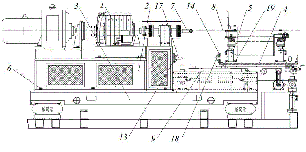
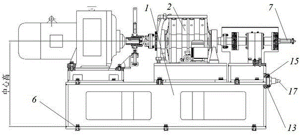
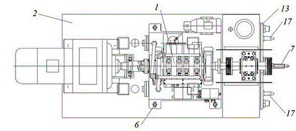
[0041] An embodiment of the present invention is figure 1 ~As shown in the figure: The engine test bench includes a bench 2 for installing the test system 1, a base 3 for installing the bench 2, and a tray 4 provided with an engine bracket 5 for installing the engine. The bench 2 passes through The bench tightening screw 6 is assembled on the front side of the base 3 of the test bench; the power input shaft of the test system 1, that is, the main shaft of the bench 2 is set towards the rear side of the bench 2, and the height of the bench main shaft 7 from the surface of the base 3 is defined as The center of the test system 1 is high. The platform 2 and the tray 4 are guided and moved through the matching male and female guide rails 10. The base 3 is provided with a male guide rail fastening screw 11 for fastening the male head guide rail 9. The tray 4 There is a female guide rail fastening screw 12 for fastening the female head guide rail 10; between the stand 2 and the tra...


PUM


Abstract

The invention discloses a centering debug method of multiple racks and trays of an engine test stand. The method comprises the following steps: optionally selecting a set of reference rack P and a set of reference tray Q, installing an engine on an engine support of the reference tray Q; adjusting the reference tray Q and the reference rack P, so as to ensure that the rack main shaft of the reference rack P and the main shaft of the engine on the reference tray Q meet the centering requirement; selecting a test stand W to be conducted to centering adjustment, and installing the reference tray Q on the test stand W; adjusting the rack of the test stand W and a guide positioning device on the base of the test stand W, so as to realize the guiding of the reference tray Q when the reference tray Q enters the test stand and the positioning of the rack, and adjusting a fastening device used for fastening the rack onto the test stand W, so as to ensure that the rack main shaft of the test stand W and the main shaft of the engine on the reference tray Q meet the centering requirement; selecting a tray N to be conducted to centering adjustment, and installing the tray N on the reference rack P; and adjusting the engine support, so as to ensure that the main shaft of the engine on the tray N and the rack main shaft of the reference rack P meet the centering requirement.

Description

technical field [0001] The invention relates to the debugging of an automatic engine test bench, in particular to the exchange and alignment debugging of a bench and a pallet. Background technique [0002] The factory inspection of the engine is a link that must be completed before each engine leaves the factory to check whether the engine has any abnormality and whether it has reached the theoretical performance of the engine. Therefore, the factory test bench of the engine has become a necessary test equipment for manufacturers. At present, there are many types of such equipment. And can realize automatic engine transportation, docking and testing. [0003] For example, Chinese Patent No. 01223188.6 discloses an integral bench for automatic engine testing, including a test system with a main shaft, a bench for installing the test system, a base for installing the bench, and extending along the front and rear docking directions A male guide rail provided on the base, and a...

Claims


Application Information

Patent Timeline
Patent Type & Authority Applications(China)
IPC IPC(8): G01M15/02
Inventor 李小亮赵小平孙丽薛鹏余任春燕程军张宏敏卢杉郭斌
Owner CAMALUOYANGELECTROMECHANIC
Why Eureka
Try Eureka