Construction method for prefabricated building shear wall conversion layer

A technology of shear walls and transfer floors, applied in the direction of buildings, building components, building structures, etc., to achieve the effect of convenient disassembly, installation and turnover, convenient turnover, and convenient disassembly

Active Publication Date: 2021-04-09
河南省第一建设集团第七建筑工程有限公司
View PDF5 Cites 5 Cited by
  • Summary
  • Abstract
  • Description
  • Claims
  • Application Information

AI Technical Summary

Problems solved by technology

[0005] In view of the above problems, the present invention provides a construction method for the transfer layer of the prefabricated building shear wall, which solves the problems mentioned in the above-mentioned background technology

Method used


Image

  • Construction method for prefabricated building shear wall conversion layer
  • Construction method for prefabricated building shear wall conversion layer
  • Construction method for prefabricated building shear wall conversion layer

Examples


Embodiment 1

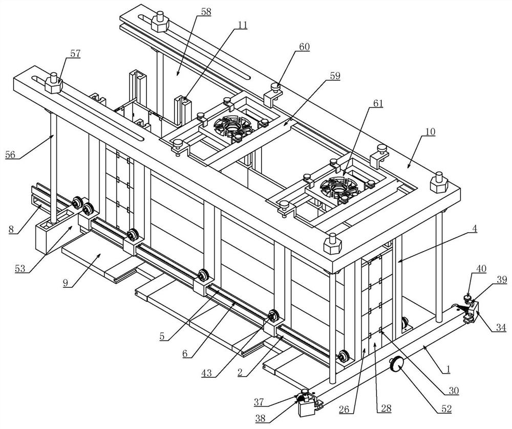
[0064]Embodiment 1, the device applying the above-mentioned prefabricated building shear wall transfer layer construction method includes a longitudinal bar 1, and the left end of the longitudinal bar 1 is open, and there are two sets of transverse bars 2 sliding longitudinally in the longitudinal bar 1, and the longitudinal bar 1 There is a groove structure with a T-shaped cross-section at the left end, and the groove structure is transparent along the front and rear directions. The end of the transverse rod 2 is a slider-shaped structure with a T-shaped cross-section. The cooperation of the two makes the two transverse rods It can move along the longitudinal direction of the longitudinal bar 1. Since the front and rear ends of the longitudinal bar 1 are in a penetrating state, the transverse bar 2 can be smoothly disengaged from the longitudinal bar 1. The longitudinal bar 1 is rotatably connected with a Two-way lead screw 3, the two-way lead screw 3 relies on the support fra...

Embodiment 2

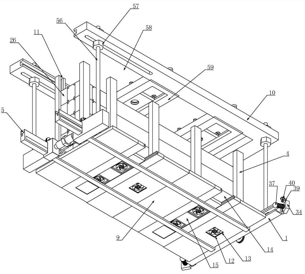
[0067] Embodiment 2, on the basis of Embodiment 1, wherein the longitudinal board 9 provided with one or more groups of movable positioning hole structures includes the body of the longitudinal board 9, and the longitudinal board 9 can adopt a wooden structure. There is a square hole 12 on the body of the longitudinal bar 1, the lower end of the square hole 12 is connected with a limit frame 13, and a positioning hole structure with a radius adjustment is placed in the square hole 12, forming a group of openings on the longitudinal plate 9. Positioning hole structure, when only one set of positioning holes is required at the lower end of the formwork structure, the positioning holes can be positioned at the corresponding positions by moving the position of the longitudinal plate 9 and according to the position of the sleeve 55 on the drawing;

[0068] The body of the longitudinal plate 9 is provided with a longitudinally transparent sliding hole 14. The sliding hole 14 is longi...

Embodiment 3

[0070] Embodiment 3, on the basis of Embodiment 1, the board structure with adjustable lateral spacing or the board structure with adjustable longitudinal spacing includes a connecting plate that cooperates with the slide rail 11 of the vertical bar 4 on the corresponding side 26. The connecting plate 26 opens in the direction of the vertical rod 4, and its interior is a box structure. The connecting plate 26 is opened with a rectangular groove 27 at one end facing the other connecting plate 26, and two sets of rectangular grooves 27 slide horizontally. Cooperate with a clamping plate 28 placed between two groups of connecting plates 26, so that the clamping plate 28 can only move along the transverse direction of the rectangular groove 27. Two sets of Us are connected to the upper and lower ends of the clamping plate 28 respectively. Shaped plate 29, the upper and lower ends of the clamp plate 28 are respectively horizontally slidably fitted with a top tightening block 30 that...


PUM


Abstract

The invention relates to a construction method for a prefabricated building shear wall conversion layer. According to the construction method, a longitudinal rod, a transverse rod and a vertical rod are matched, the longitudinal rod and the transverse rod are connected through a lead screw, and therefore the longitudinal rod and the transverse rod are convenient to drive and move and convenient to disassemble; the transverse rod and the vertical rod are matched through ratchets and pawls to achieve formwork positioning, and meanwhile the vertical rod and the transverse rod are convenient to disassemble through an unlocking device; the ends are locked through a clamping device, a guide rail is arranged on the vertical rod, a formwork structure is installed in the guide rail to form a rectangular formwork frame structure, and disassembling, assembling and transferring are convenient; and meanwhile, inserting steel bar positions are positioned through sleeve positioning devices on the upper portion and the lower portion of a formwork frame, and after the upper ends and the lower ends of sleeves are locked, deviation cannot occur in the concrete pouring and vibrating process. According to the construction method, sleeve steel bars are accurately positioned and are not prone to deviation or deformation, transferring is convenient, formworks are convenient to disassemble, assemble and use, the practicability is high, and the construction method is suitable for application and popularization.

Description

technical field [0001] The invention belongs to the technical field of construction equipment methods, and in particular relates to a construction method for a transition layer of a prefabricated building shear wall. Background technique [0002] At present, under the background of vigorously promoting the transformation of economic development mode, adjusting industrial structure and vigorously promoting energy conservation and emission reduction in China, local governments have introduced local policies to support the development of construction industrialization, focusing on affordable housing construction. Domestic large-scale real estate development companies, general contracting companies and prefabricated component manufacturers have also taken action to increase investment in construction industrialization. From a national perspective, the construction industrialization represented by the rapid development of new prefabricated concrete assembly structures has entered...

Claims


Application Information

Patent Timeline
Patent Type & Authority Applications(China)
IPC IPC(8): E04B2/00E04G21/00E04G11/08E04G17/00E04G17/075
CPCE04B2/00E04G21/00E04G11/08E04G17/00E04G17/0755E04G2017/008
Inventor 周建设胡凌云张松涛何小宁张德鹏郭旗张瑞瑞王坤王小龙郭建光袁兵张春贾志浩
Owner 河南省第一建设集团第七建筑工程有限公司
Why Eureka
Try Eureka