Annular resistor film correction method

A resistive film and ring technology, applied in resistors, resistor manufacturing, circuits, etc., can solve problems affecting the accuracy of measurement, and achieve the effect of improving measurement accuracy and simplifying the process of measurement and repair.

Active Publication Date: 2013-02-27
SICHUAN AEROSPACE FENGHUO SERVO CONTROL TECH CO LTD
View PDF6 Cites 0 Cited by
  • Summary
  • Abstract
  • Description
  • Claims
  • Application Information

AI Technical Summary

Problems solved by technology

[0005] In view of this, the present invention provides a ring-shaped resistance diaphragm correction method to solve the problem in the prior art that the correction technology affects the accuracy of the measurement. The specific scheme is as follows:

Method used


Image

  • Annular resistor film correction method
  • Annular resistor film correction method
  • Annular resistor film correction method

Examples


Embodiment Construction

[0030] The following will clearly and completely describe the technical solutions in the embodiments of the present invention with reference to the accompanying drawings in the embodiments of the present invention. Obviously, the described embodiments are only some, not all, embodiments of the present invention. Based on the embodiments of the present invention, all other embodiments obtained by persons of ordinary skill in the art without making creative efforts belong to the protection scope of the present invention.

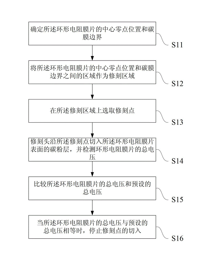
[0031] The flow chart of the ring-shaped resistance diaphragm correction method disclosed by the present invention is as follows: figure 1 shown, including:

[0032] Step S11, determining the center zero position of the annular resistance diaphragm and the carbon film boundary;

[0033] The determination of the central zero point of the annular resistance diaphragm and the position of the carbon film boundary is the basis for the correction of the annular res...


PUM


Abstract

The invention discloses an annular resistor film correction method. The correction method comprises the steps of: incising a carbon powder layer on the surface of an annular resistor film by use of a repair head to change the thickness of the carbon powder layer so as to change the total voltage of the annular resistor film; and stopping incising when the total voltage of the annular resistor film is equal to a preset total voltage to complete incision of the point. According to the method, an electric brush during processing can be omitted by introducing a total voltage feedback algorithm, thereby improving the measurement accuracy and simplifying the measurement and incision process.

Description

technical field [0001] The invention relates to the field of sensor manufacturing, in particular to a ring-shaped resistance diaphragm correction method. Background technique [0002] During the manufacturing process of the ring-shaped composite membrane potentiometer, the ring-shaped resistance diaphragm needs to be repaired and engraved to make the scale of the ring-shaped composite membrane potentiometer accurate. At present, the method of repairing and engraving the ring-shaped resistive diaphragm is generally adopted while measuring and engraving. According to the different power supply methods, it can be divided into two types, one is constant voltage source power supply, and the other is constant current source powered by. [0003] However, during the trimming process powered by a constant voltage source, the contact resistance of the brush will be introduced into the overall circuit, thereby affecting the measurement accuracy. During the repairing process powered b...

Claims


Application Information

Patent Timeline
Patent Type & Authority Applications(China)
IPC IPC(8): H01C17/235
Inventor 左湘汉王惠峰濛淑红王广林曾好
Owner SICHUAN AEROSPACE FENGHUO SERVO CONTROL TECH CO LTD
Why Eureka
Try Eureka