Wireless electric energy transmission magnetic coupling structure and circuit of wireless electric energy transmission magnetic coupling structure

A wireless energy transmission and magnetic structure technology, applied in the field of energy transmission, can solve the problems of large magnetic field leakage radiation range, electromagnetic interference, and poor power transmission efficiency, and achieve the effects of small magnetic field diffusion range, large coupling coefficient, and high transmission efficiency

Active Publication Date: 2013-02-27
FUZHOU UNIV
View PDF7 Cites 29 Cited by
  • Summary
  • Abstract
  • Description
  • Claims
  • Application Information

AI Technical Summary

Problems solved by technology

[0009] a. The magnetic induction coupling coefficient of the transmitting and receiving sides is low, and the power transmission efficiency is poor; especially, it cannot be well applied to the case where the magnetic structure of the receiving side is arbitrarily offset from the magnetic structure of the transmitting side;
[0010] b. The magnetic field leakage radiation range generated by the magnetic structure on the transmitting side is large, which will bring a wide range of electromagnetic interference problems

Method used


Image

  • Wireless electric energy transmission magnetic coupling structure and circuit of wireless electric energy transmission magnetic coupling structure
  • Wireless electric energy transmission magnetic coupling structure and circuit of wireless electric energy transmission magnetic coupling structure
  • Wireless electric energy transmission magnetic coupling structure and circuit of wireless electric energy transmission magnetic coupling structure

Examples


Embodiment Construction

[0048] In order to make the above-mentioned features and advantages of the present invention more comprehensible, the following specific embodiments are described in detail with reference to the accompanying drawings.

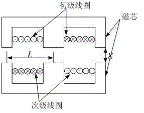
[0049] refer to Figure 8 to Figure 25 , The present invention relates to a magnetic coupling structure for wireless power transmission, including a transmitting-side magnetic structure 1 and a receiving-side magnetic structure 2. The transmitting-side magnetic structure 1 is composed of a plurality of rectangular coils 3, and the rectangular coils 3 are distributed in a zigzag shape. The current flow distribution generated by it forms an opposite flow direction between adjacent rectangular loops, and the coil 3 on the transmitting side forms a magnetic field transmitting plane, and the radiated magnetic field can be controlled within a certain range; the magnetic structure 2 on the receiving side It includes coil groups 4 respectively arranged in three orthogo...


PUM


Abstract

The invention relates to a wireless electric energy transmission magnetic coupling structure, which comprises a magnetic structure at the transmission side and a magnetic structure at the receiving side. The structure is characterized in that the magnetic structure at the transmission side consists of a plurality of rectangular coils, the rectangular coils are distributed in a delta shape, the generated current flows and distributes between adjacent rectangular loops in a reverse flowing direction, the coils at the transmission side form a magnetic field transmission plane, the magnetic structure at the receiving side comprises coil groups which are respectively arranged in three orthogonal directions, and the coil groups respectively induce the magnetic field components in the three orthogonal directions. The structure has the advantages that the coupling coefficient is higher, the electric energy transmission efficiency is higher, the electromagnetic interference on the surrounding space is little, and the structure is widely applied to wireless electric energy transmission systems with various power grades.

Description

technical field [0001] The invention relates to a wireless energy transmission magnetic coupling structure and a circuit thereof, belonging to the field of energy transmission. Background technique [0002] Wireless inductive power transfer is the transmission of electric power through indirect electrical conduction. At present, the electric power is transmitted from the magnetic structure on the transmitting side (TX) to the magnetic structure on the receiving side (RX) through space induction mainly through high-frequency magnetic field coupling. In order to improve wireless power transmission To improve efficiency and reduce electromagnetic interference, the magnetic coupling structure on the transmitting and receiving sides becomes the key technology of wireless power transmission. Especially in many wireless charging applications, such as electric vehicle wireless inductive charging, desktop wireless inductive charging, etc., the receiving side is generally a certain di...

Claims


Application Information

Patent Timeline
Patent Type & Authority Applications(China)
IPC IPC(8): H02J17/00H01F38/14H02J50/10
Inventor 陈为黄晓生谢文燕陈庆彬
Owner FUZHOU UNIV
Why Eureka
Try Eureka