
Frequency dividing circuit of I2S (inter-IC sound) interface clock circuit

A technology of clock circuit and frequency division circuit, which is applied in electrical components, counting chain pulse counters, pulse counters, etc. It can solve the problems of crystal oscillators that cannot meet the audio signal transmission of multiple sampling frequencies, high cost, cost reduction, and chip area. , to achieve the effect of reducing area, reducing use and reducing cost

Inactive Publication Date: 2013-02-27
SOUTHEAST UNIV
View PDF2 Cites 3 Cited by
  • Summary
  • Abstract
  • Description
  • Claims
  • Application Information

AI Technical Summary

Problems solved by technology

[0005] The present invention aims at the problem of high cost in the prior art, and the problem that some specific crystal oscillators cannot meet the audio signal transmission of multiple sampling frequencies, and provides a new digital audio I2S interface clock circuit frequency division circuit and method. The circuit of the method does not need to add additional phase-locked loops and crystal oscillators, so the cost and chip area can be reduced

Method used


Image

  • Frequency dividing circuit of I2S (inter-IC sound) interface clock circuit
  • Frequency dividing circuit of I2S (inter-IC sound) interface clock circuit
  • Frequency dividing circuit of I2S (inter-IC sound) interface clock circuit

Examples


Embodiment Construction

[0020] In order to make the above objects, features and advantages of the present invention more comprehensible, the present invention will be further described in detail below in conjunction with the accompanying drawings and specific embodiments.

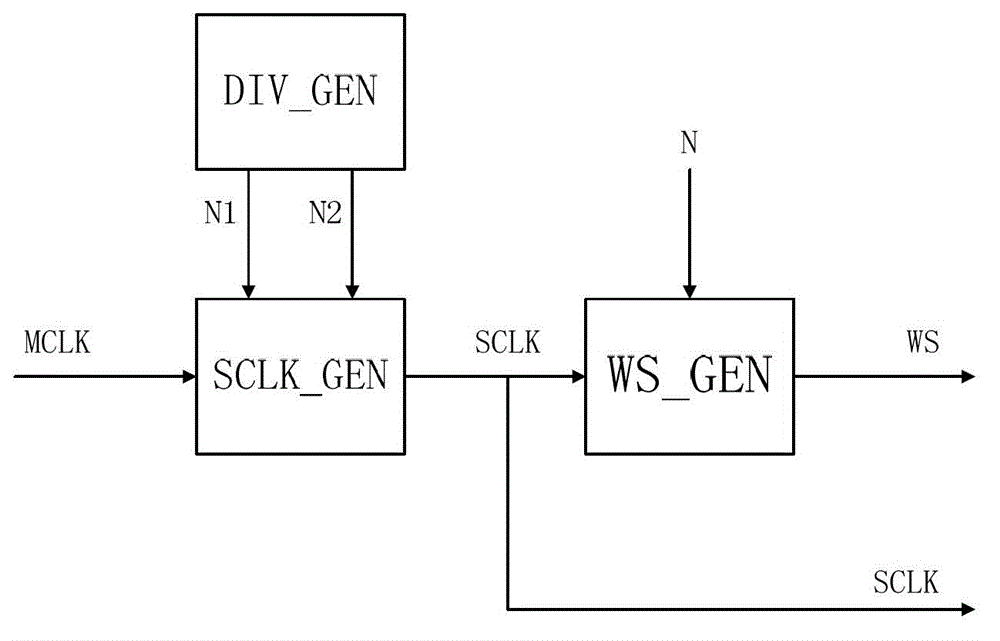
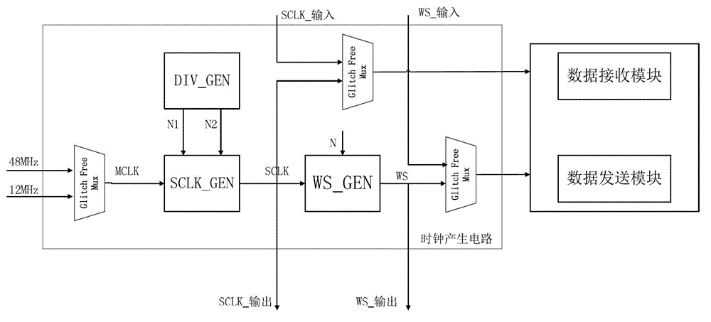
[0021] Aiming at the problems of increased cost and increased area caused by adding phase-locked loop circuits and additional crystal oscillators in the existing audio clock generation circuit technology, the present invention creatively proposes a method that utilizes the original 12MHz and 48MHz clocks of the chip system to generate and support all Sampling frequency of the serial bit clock SCLK mechanism.

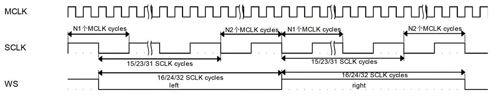
[0022] In the implementation example of the present invention, the frequency division factor generation module (DIV_GEN) calculates two values ​​of the frequency division factors N1 and N2 according to the MCLK frequency, the required sampling frequency (the frequency of the WS signal), and ws_length, where N1 must be an even...


PUM


Abstract

The invention relates to a frequency dividing circuit of a serial digital audio bus I2S (inter-IC sound) interface clock circuit. The frequency dividing circuit comprises a serial clock SCLK generating module SCLK_GEN, a field selection signal WS generating module WS_GEN and a configuration frequency dividing factor module DIV_GEN. A method comprises the following steps that 1) the DIV_GEN calculates two values of frequency division factors N1 and N2 according to the frequency value Fmclk of the I2S main clock MCLK, the sampling frequency FWS, i.e. the field selection signal WS signal frequency and the sampling digit ws_length, wherein the N1 value is the even number; 2) N1 and N2 are input into the SCLK_GEN, and the SCLK_GEN generates the serial clock SCLK; and 3) the SCLK is input into the WS_GEN, and the WS_GEN generates WS; and the WS_GEN is a configurable frequency divider, and the frequency dividing value N is equal to ws_length*2. The frequency dividing circuit has the advantages that the two frequency dividing factors are utilized, the different-period SCLK is obtained through MCLK frequency division, further, corresponding WS signals are generated, the use of PLL (phase locked loop) circuits and additional crystal oscillators is reduced, and the goals of lowering the cost and reducing the area are reached.

Description

technical field [0001] The invention relates to a clock frequency division circuit and a method for an ASIC chip in the field of digital integrated circuits, in particular to a clock frequency division circuit for an I2S interface of a digital multimedia system. Background technique [0002] In today's digital age, System On Chip (SOC) and Application Specific Integrated Circuit (ASIC) technologies are developing rapidly, and mobile electronic multimedia devices with SoC chips as the core have penetrated into people's daily life. Acquisition, processing and transmission of audio data is an important part of multimedia technology. At present, a major digital audio transmission standard is the I2S (Inter-IC Sound) bus interface protocol developed by Philips, which specifies the format of digital audio data. A serial transmission bit clock SCLK and a frame clock WS are required. [0003] According to different audio file formats and different application scenarios, the sampli...

Claims


Application Information

Patent Timeline
Patent Type & Authority Applications(China)
IPC IPC(8): H03K23/00
Inventor 刘新宁王镇杨军曹华洋孙声震张亚伟
Owner SOUTHEAST UNIV
Learn More