
Compressor and turbomachine with optimized efficiency

A turbine engine and compressor technology, applied in the field of axial flow compressors, can solve the problems of reduced pumping margin, small improvement, and no improvement in pumping margin, so as to achieve good pumping margin and good interaction effect, good efficiency

Active Publication Date: 2013-02-27
SN DETUDE & DE CONSTR DE MOTEURS DAVIATION S N E C M A
View PDF9 Cites 2 Cited by
  • Summary
  • Abstract
  • Description
  • Claims
  • Application Information

AI Technical Summary

Problems solved by technology

[0008] So this groove in the compressor gives an improvement in the efficiency of the compressor, but the improvement is very small, and also, there is no improvement in the pumping margin, and it may even reduce the pumping margin

Method used


Image

  • Compressor and turbomachine with optimized efficiency
  • Compressor and turbomachine with optimized efficiency
  • Compressor and turbomachine with optimized efficiency

Examples


Embodiment Construction

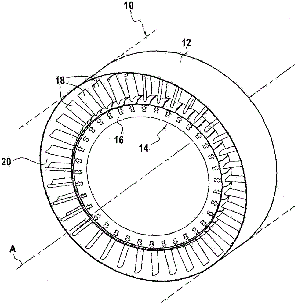
[0047] figure 1 An axial compressor of turbine engine 10 is shown. The compressor has a housing 12 in which a rotor wheel 14 is mounted. The rotor wheel 14 itself comprises a rotor disk 16 to which radial blades 18 are fixed in an axisymmetric configuration in a known manner. The rotor wheel is arranged rotatable about an axis of rotation A in the housing 12 .

[0048] Box 12 has an interior wall 20 of generally shaped shape that defines an aerodynamic reference surface 22 (see image 3 ), the aerodynamic reference surface defines the channels through which the gas can pass. The aerodynamic reference surface is a surface of revolution, generally substantially conical in shape, in this example cylindrical.

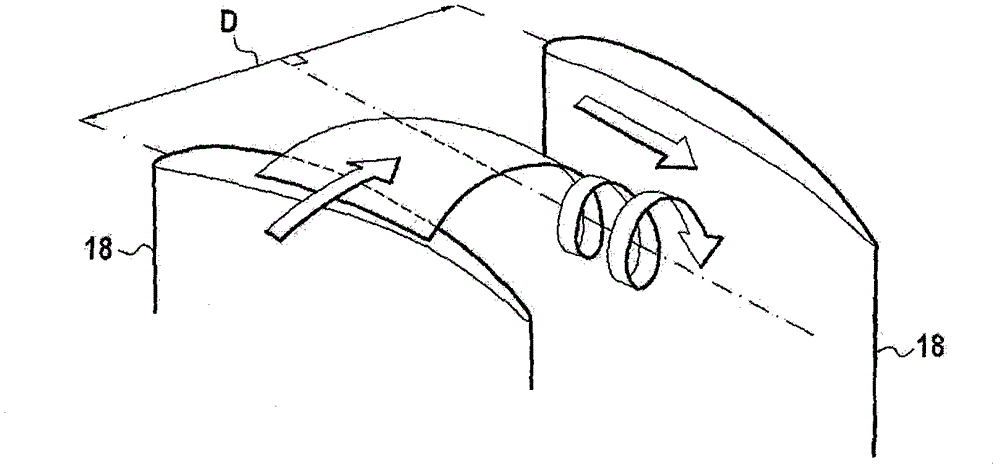
[0049] refer to image 3 The arrangement of the blades 18 and the inner wall 20 for reducing the gap vortex in the compressor of the present invention will be described.

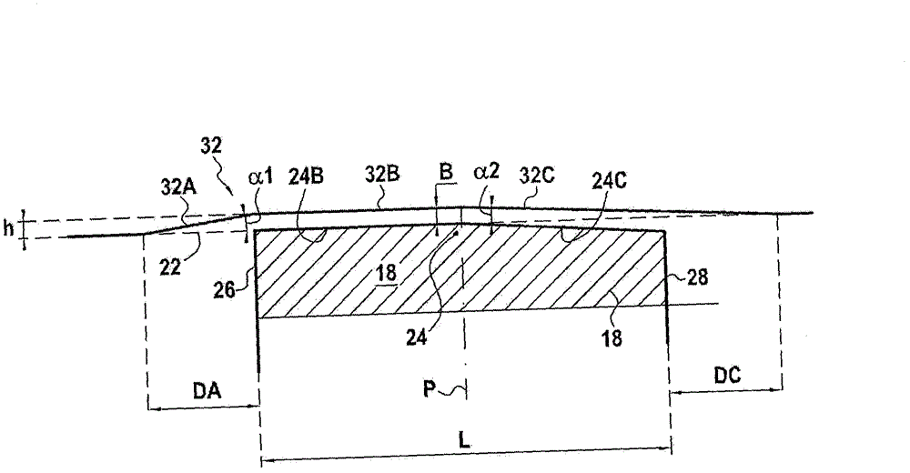
[0050] Such as image 3 As shown, each blade has a leading edge 26, a trailing edge 28 and a ra...


PUM


Abstract

Turbomachine compressor (10) comprising a casing (12) of which an inner wall defines an aerodynamic reference surface delimiting a gas flow duct, and in which there is mounted a bladed wheel (14) equipped with radial blades (18). A circumferential groove is formed in the inner wall of the casing. Its shape is defined from upstream to downstream by three substantially conical surfaces, an upstream surface, a central surface and a downstream surface, respectively. The upstream surface extends upstream of the leading edge of the blades. The central surface is substantially parallel to said aerodynamic reference surface. The downstream surface extends downstream at least as far as the trailing edge of the blades. The junction between the central and downstream surfaces is situated between 30% and 80%, preferably between 50 and 65%, of the axial length of the blades (18) starting from the leading edge.

Description

technical field [0001] The invention relates to an axial compressor for a turbine engine. Background technique [0002] Such compressors typically include a housing in which is rotatably mounted a rotor wheel having a set of radial blades each having a wing tip, a leading edge and a trailing edge. Usually, these blades are arranged in such a way that their wing tips pass as close as possible to the inner wall of the box. [0003] However, a gap must be left between the blade tip and the inner wall of the box. Thus, as the impeller rotates relative to the casing, air (or more generally fluid) flows from the pressure side to the suction side through the gap between the blades and the casing. This flow is very violent and, as a result, creates eddies known as "interstitial" vortices, which can lead to a reduction in compressor efficiency, as the interaction between the interstitial eddies and the boundary layer present on the casing walls increases. Larger, this effect will ...

Claims


Application Information

Patent Timeline
IPC IPC(8): F04D29/52F04D29/68F01D5/14F01D5/20
CPCF01D5/143F05B2250/314F05D2260/2212F01D5/145F04D29/526F04D29/522F01D5/20F04D29/681F05D2250/232F05D2250/314F05B2250/232F05B2260/222F04D29/547F04D29/68F04D29/545F04D19/00
Inventor 文森特·保罗·盖布里埃尔·佩罗特艾格尼丝·帕斯蒂尔莱文·巴特瓦西利基·伊利普罗
Owner SN DETUDE & DE CONSTR DE MOTEURS DAVIATION S N E C M A
Features
  • Generate Ideas
  • Intellectual Property
  • Life Sciences
  • Materials
  • Tech Scout
  • Unparalleled Data Quality
  • Higher Quality Content
  • 60% Fewer Hallucinations
Learn More