
Card dividing device and automatic electrical writing device with the same

A card device, electric writing technology, applied in sorting, instruments, digital marking record carriers, etc., can solve the problems of poor chain transmission stability, and achieve the effect of ensuring accuracy, saving costs and saving space

Active Publication Date: 2016-09-07
INT SECURITY TECH SHENZHEN +1
View PDF9 Cites 0 Cited by
  • Summary
  • Abstract
  • Description
  • Claims
  • Application Information

AI Technical Summary

Problems solved by technology

Each separated card falls freely to the chip information reading part through the shaking surface slideway to read the information in the chip, and enters the card collection mechanism for classification according to the specified procedure; the card collection mechanism uses a chain as the transport carrier, and each slot Each position has its own stepping motor to control the flap to realize the sorting of cards. This scheme only provides a solution for sorting finished cards, and the stability of the chain transmission is poor. Find a stable Card-splitting method is the first problem that the present invention needs to solve
[0004] "Design of Automatic Electronic Writing Machine for Resident ID Card", The First Research Institute of the Ministry of Public Security, Li Jianmin, Mou Yuetai, Wang Zhixuan, Police Technology, pp. 46-47, January 2007, disclosed an automatic electronic writing machine, The card splitting mechanism adopts the card splitting method that is pushed flatly from the bottom of the feeding box. It can accommodate 500 ID card single cards. Place the feeding box on the holder of the feeding box. There is a card outlet with the same length as the ID card length of 85.5mm. The thickness is about 1.2mm, and the direction can be pressed upwards. It is necessary to adjust the stepping motor to drive the eccentric link mechanism to convert the rotary motion into a linear motion. Every time it rotates, the connecting rod drives the ball guide rail to push the card dividing guide block in the horizontal direction, and the card separating guide block is ejected from the bottom of the feeding box. Push out a card in the mouth to achieve the purpose of card separation. The height of the card outlet at the bottom of the feeding box can be adjusted arbitrarily, so that the structure is simple and the function is reliable. At this time, the application software uses OCR to read the ID card number, then organizes the writing of card information, writes the information into the initialized chip, and finally verifies the correctness of the information written. The solution of information writing and information inspection, and the classification of cards after the card writing inspection is completed, did not give a solution, and how to deal with the cards that failed the inspection of card information writing, these have not been resolved

Method used


Image

  • Card dividing device and automatic electrical writing device with the same
  • Card dividing device and automatic electrical writing device with the same
  • Card dividing device and automatic electrical writing device with the same

Examples


Embodiment Construction

[0023] Attached below Figure 1-5 Detailed explanation is carried out to the card dividing device 2 of the present invention:

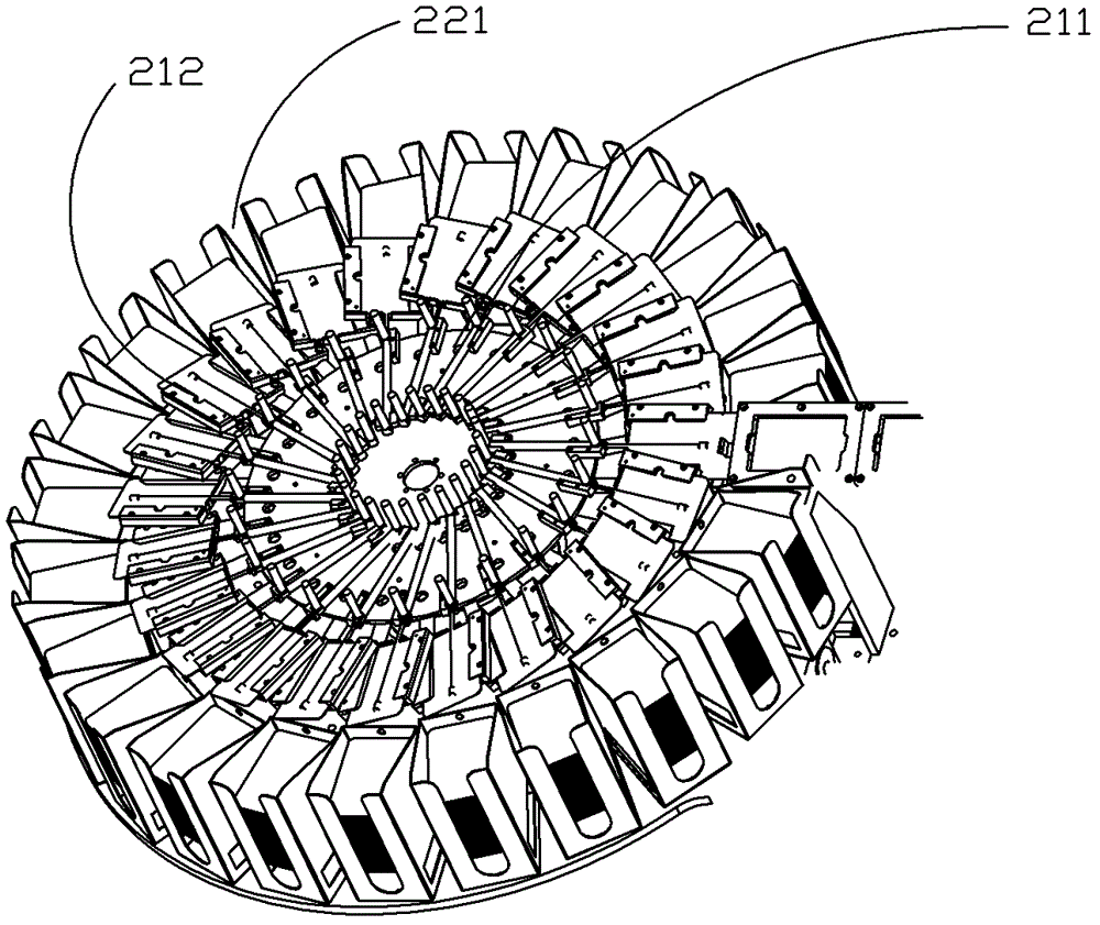
[0024] figure 1 It is a schematic diagram of the combination of the first layer sub-chuck 211 and the second layer sub-chuck 221 of the present invention. The first layer sub-chuck can rotate relative to the second layer sub-chuck. Temporary card storage slot 212, the temporary card storage slot and the horizontal plane form an acute angle, and the temporary card storage slots are superimposed on each other and located on the first layer of sub-chucks.

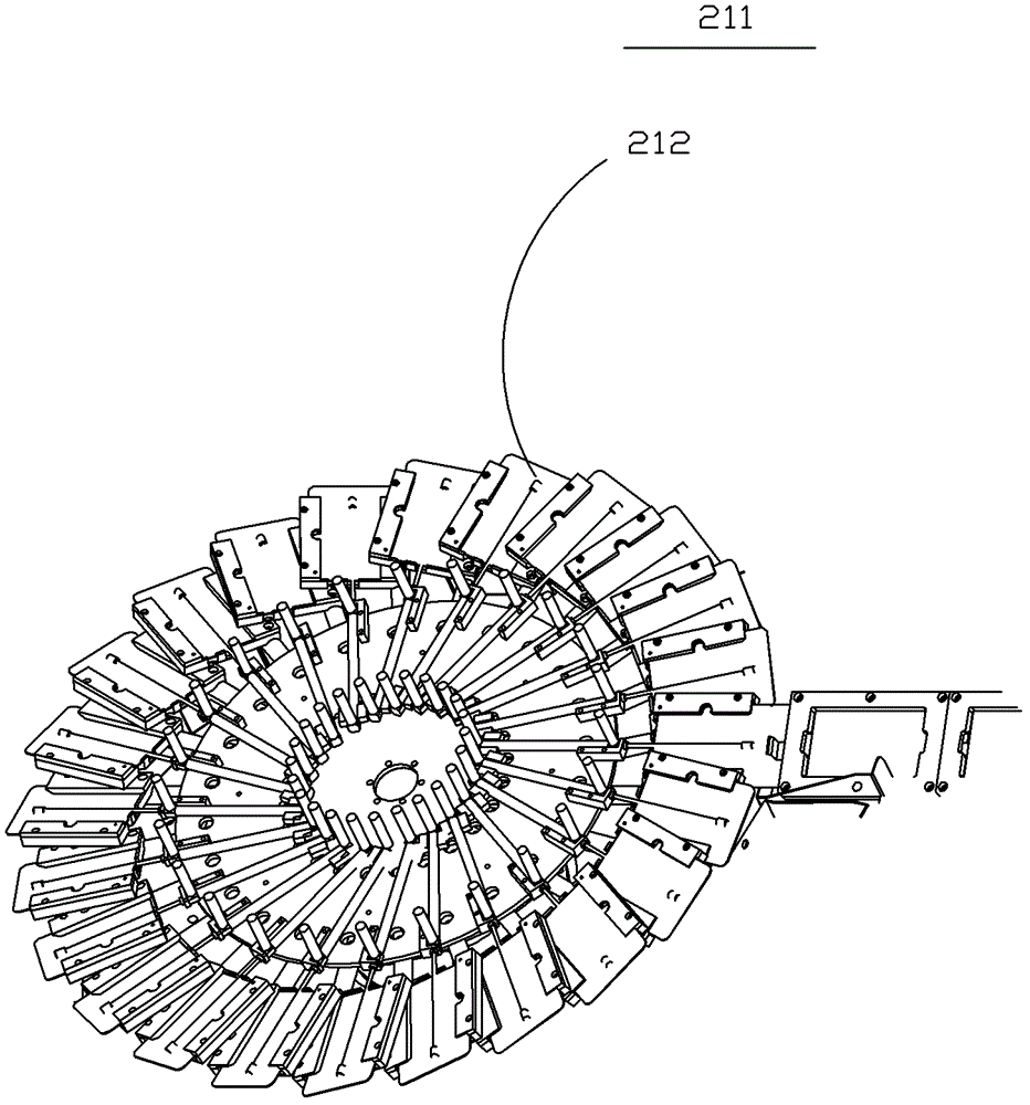
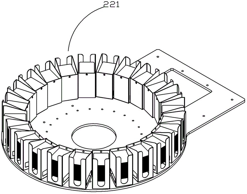
[0025] Figure 2a It is a schematic diagram of the structure of the first layer sub-chuck 211 of the present invention. The card temporary storage slot 212 forms an acute angle with the horizontal plane. slot; Figure 2b It is a structural schematic diagram of the second layer of the sub-chuck of the present invention. The storage card slots are located on the second layer of the sub-chucks, arran...


PUM


Abstract

The invention provides a card sorting device and an automatic electric writing device with the same. The card sorting device comprises a card sorting plate and a rotating shaft, wherein the rotating shaft is horizontally positioned at the lower part of the card sorting plate; the card sorting plate is divided into two layers, namely, a first layer for installing an identification card temporary storage slot, and a second layer for installing a card storage slot, and the first layer can be rotated relative to the second layer; bulges, which are arranged along the circumference, are arranged at the lower bottom part of the first layer of the card sorting plate; a card pushing device for pushing an identification card out of the temporary storage slot is arranged on the card sorting plate; cam mechanisms in match with the bulges at the lower bottom part of the first layer of the card sorting plate are arranged at the end part of the rotating shaft; the automatic electric writing device comprises a base, a card feeding device, a card writing device, an information verifying device, an information processing device and the card sorting device, and the information processing device is positioned in the base; the card feeding device is positioned on the base; the card writing device and the information verifying device are positioned at the upper part of the card feeding device; and the card sorting device is positioned at the tail end of the card feeding device. The card sorting plate has the advantages of being stable, high in sorting capacity, high in efficiency, and small in size.

Description

【Technical field】 [0001] The invention relates to a card sorting device and an automatic electric writing device with the card sorting device, in particular to a device for classifying information on cards and an automatic electric writing device equipped with the sorting device . 【Background technique】 [0002] Cards are playing an increasingly important role in life and learning. Today's card production takes into account the application in the information age and integrates more information into the card. For example, the card will be The surface information of the card is electronically written to the chip inside the card. However, how to classify and screen the cards after card making is a new problem. There may be thousands or more cards produced at one time. After the production is completed, it is a very heavy task to manually classify the cards, and the integrity of the card information cannot be guaranteed. If the information is written in the electronic card At...

Claims


Application Information

Patent Timeline
Patent Type & Authority Patents(China)
IPC IPC(8): B07C5/36G06K1/12
Inventor 严金波
Owner INT SECURITY TECH SHENZHEN
Learn More