Porous clamping device capable of automatically centering and drilling long-thin steel-sheet type parts

A technology of automatic centering and clamping device, which is applied in positioning devices, drilling dies for workpieces, metal processing machinery parts, etc. , low punching accuracy, etc., to achieve the effect of short cycle, simple clamping and high punching accuracy

Active Publication Date: 2013-03-06
HARBIN JIANCHENG GRP
View PDF5 Cites 12 Cited by
  • Summary
  • Abstract
  • Description
  • Claims
  • Application Information

AI Technical Summary

Problems solved by technology

[0003] The purpose of the present invention is to solve the problem of the complex structure of the porous machining mold for long and thin steel parts, long processing cycle and high cost, and the center line of the punching hole is prone to deflection, the punching precision is low, and it is difficult to ensure the long and thin steel parts. To solve the problem of porous processing quality, provide an automatic centering drilling and clamping device for long and thin steel parts

Method used


Image

  • Porous clamping device capable of automatically centering and drilling long-thin steel-sheet type parts
  • Porous clamping device capable of automatically centering and drilling long-thin steel-sheet type parts
  • Porous clamping device capable of automatically centering and drilling long-thin steel-sheet type parts

Examples


specific Embodiment approach 1

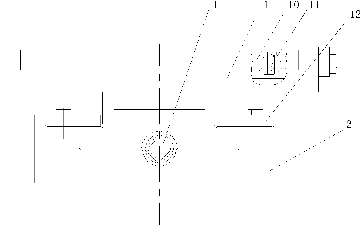
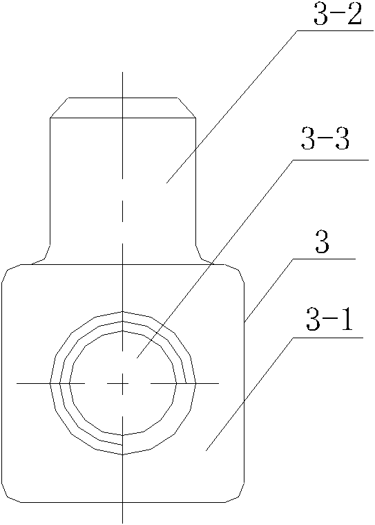
[0009] Specific implementation mode one: combine Figure 1-Figure 16 Illustrate, the multi-hole clamping device for automatic centering drilling of long and thin steel plates in this embodiment, the device includes a base 2, the base 2 is in the shape of a cuboid; the device also includes a screw rod 1, claws 4, side plates 6, top Wire 7, sliding top block 8, mold body 10, a plurality of drill sleeves 11, two nuts 3 and two pressing plates 12; the nut 3 is made up of an integrated square body end 3-1 and a cylindrical rod 3-2 , the side wall of the square body end 3-1 is provided with a through threaded through hole 3-3; the claw 4 includes a first sliding table 4-1, a first limiting table 4-2 and a baffle plate 4-3; The first sliding platform 4-1 is located at the bottom of the first limiting platform 4-2 and is integrated with the first limiting platform 4-2; the sliding top block 8 includes the second sliding platform 8-1 and the second limiting platform 8-2; the second sl...

specific Embodiment approach 2

[0011] Specific implementation mode two: combination figure 1 and Figure 5 Note that both ends of the screw rod 1 in this embodiment are flat ends 1-2. Designed in this way, use the jaws to fix it. Others are the same as in the first embodiment.

specific Embodiment approach 3

[0012] Specific implementation mode three: combination figure 1 , figure 2 , Figure 14 and Figure 15 To illustrate, the base 2 of this embodiment is a cast steel base. Such design, good wear resistance. Others are the same as in the first or second embodiment.


PUM


Abstract

A porous clamp device capable of automatically centering and drilling long-thin steel-sheet type parts relates to a porous centering and drilling clamp device for long-thin steel sheets, and solves the problem that a porous processing mold for the long-thin steel sheets is complex in structure, long in processing period, high in cost, low in punching accuracy and the like. A claw and a sliding top block are slidingly matched with two first sliding chutes on a base, two nuts are arranged in two second sliding chutes on the base and slidingly matched with the second sliding chutes and fixed with the claw and the sliding top block, a stop plate is arranged on the claw which is detachably connected with a slide plate, an inverted isosceles trapezoid groove and a long groove for storing drilling parts are formed between the claw and the sliding top block, a mold is inverted in the isosceles trapezoid groove, a fastening screw leans on the mold, a drill bushing is inlaid in a drilling bushing hole of the mold, a positioning block of a screw rod is arranged in a screw rod support seat on the base, and two ends of the screw rod are connected with the two nuts in a threaded manner. The porous clamp device is used for clamping and fixing in drilling of the long-thin steel-sheet type parts.

Description

technical field [0001] The invention relates to a multi-hole clamping device for centering drilling of long and thin steel plate parts. Background technique [0002] When drilling long and thin steel parts, conventional stamping and punching processing methods are often used. The punching process of long and thin steel parts requires the design of a special die, which has complex structure, long processing cycle and high cost, and the center line of the punched hole is prone to deflection, and the punching accuracy is low, so it is difficult to ensure the porousness of long and thin steel parts. Processing quality. Contents of the invention [0003] The purpose of the present invention is to solve the problem of the complex structure of the porous machining mold for long and thin steel parts, long processing cycle and high cost, and the center line of the punching hole is prone to deflection, the punching precision is low, and it is difficult to ensure the long and thin s...

Claims


Application Information

Patent Timeline
Patent Type & Authority Applications(China)
IPC IPC(8): B23B47/28B23Q3/06
Inventor 武晓燕赵源东程国锋曾庆富
Owner HARBIN JIANCHENG GRP
Why Eureka
Try Eureka