
Perforated pipe burr removing machine

A technology of deburring machine and perforated tube, which is applied in the directions of cleaning hollow objects, cleaning methods and utensils, chemical instruments and methods, etc. Strength, the effect of avoiding the phenomenon of knife jamming

Active Publication Date: 2014-11-19
ANTON OILFIELD SERVICES (GRP) LTD
View PDF5 Cites 0 Cited by
  • Summary
  • Abstract
  • Description
  • Claims
  • Application Information

AI Technical Summary

Problems solved by technology

The existing technology relies on manpower to remove the burrs on the inner wall of the perforated pipe through pneumatic tools or punches, which is not clean and labor-intensive

Method used


Image

  • Perforated pipe burr removing machine
  • Perforated pipe burr removing machine
  • Perforated pipe burr removing machine

Examples


Embodiment Construction

[0027] The present invention will be further described in detail below with reference to the drawings and specific embodiments, but it is not intended to limit the present invention.

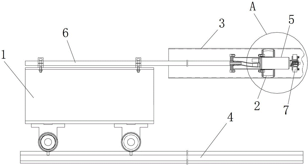
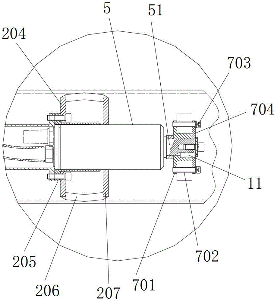
[0028] figure 1 It is a schematic diagram of the structure of the perforated tube deburring machine of the present invention; figure 2 for figure 1 Enlarged view of part A of. Such as figure 1 with figure 2 As shown, the perforated tube deburring machine includes a rail car 1 that moves linearly along a rail 4, and a support arm 6 parallel to the rail 4 is fixed on the rail car 1. A rotation driving device 5 is connected to the front end of the support arm 6. A cutter 7 is fixed to the rotary drive shaft 51 of the rotary drive device 5.

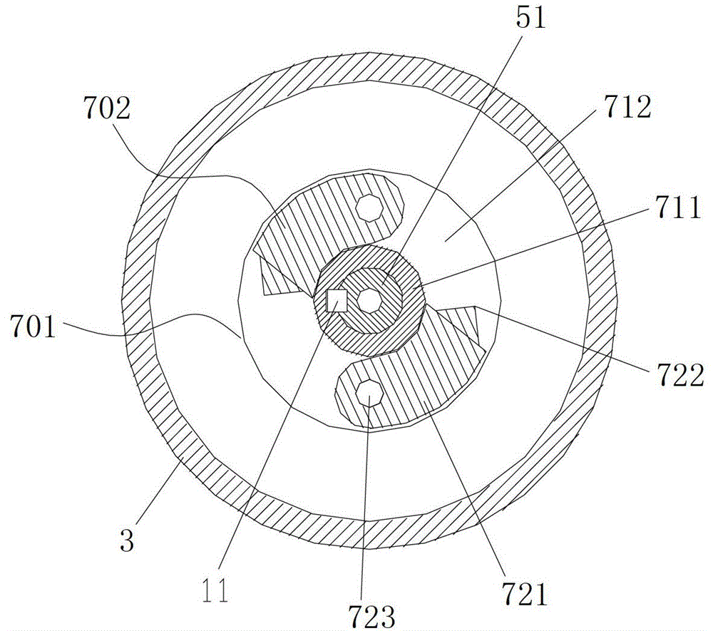
[0029] image 3 It is a schematic cross-sectional view of the cutter part of the perforated tube deburring machine of the present invention. Combine figure 1 , figure 2 with image 3 The tool 7 includes a tool holder 701 fixed to the rotating drive shaft and at...


PUM


Abstract

The invention discloses a perforated pipe burr removing machine, which comprises a track car which can linearly move along tracks. A supporting arm which is in parallel with the tracks is fixedly arranged on the track car. The front end of the supporting arm is connected with a rotary driving device. A cutter is fixedly arranged on the rotary driving shaft of the rotary driving device. The perforated pipe burr removing machine has the advantages that the burr removing effect is good and the labor intensity is reduced.

Description

Technical field [0001] The invention relates to the technical field of pipe fitting processing equipment, in particular to a perforated pipe deburring machine. Background technique [0002] The length of the perforated pipe is about 10 meters, and the pipe wall has dense holes. The inner wall of the perforated tube has a lot of burrs generated during perforation, and a deburring machine needs to be used to remove the burrs. In the prior art of the perforated tube deburring machine, there are mainly two deburring methods. One is to hold the steel air tube by a person, insert a pneumatic tool (reformed with a wind grinder) into the perforated tube, and repeat it manually. Push and pull movement to remove burrs on the inner wall of the perforated pipe. The other is to rely on people to hold the steel bar, insert the punch into the perforated tube, and repeatedly push and pull manually to remove the burrs on the inner wall of the perforated tube. In the prior art, the burr on the ...

Claims


Application Information

Patent Timeline
Patent Type & Authority Patents(China)
IPC IPC(8): B08B9/049
Inventor 代长付姜士湖李世国杨志清
Owner ANTON OILFIELD SERVICES (GRP) LTD
Learn More