
Method for reducing rudder resistance of ships

A technology of rudders and ships, which is applied in ship construction, rudder steering, hull and other directions to achieve the effect of reducing resistance

Inactive Publication Date: 2013-03-06
林瑞麟
View PDF4 Cites 5 Cited by
  • Summary
  • Abstract
  • Description
  • Claims
  • Application Information

AI Technical Summary

Problems solved by technology

Therefore, the resistance produced by the ship's rudder 14 in the high-speed water flow of the propeller 13 is unavoidable
[0004] But, in prior art, solve above-mentioned problem point, mostly be under the principle that this ship rudder does not affect structural strength, can only design streamlined on shape or do surface treatment, reduce the resistance of ship's rudder
However, these methods can actually reduce the effect of resistance, either still need to be improved, or cost a lot of money; therefore, how to reduce the resistance of the ship's rudder at low cost, and then reduce fuel consumption, has been asked by ship manufacturers. Even the problems that academic research units want to solve

Method used


Image

  • Method for reducing rudder resistance of ships
  • Method for reducing rudder resistance of ships
  • Method for reducing rudder resistance of ships

Examples


Embodiment Construction

[0044] The following provides preferred embodiments aiming at the above-mentioned technical features of the present invention. However, there are many types of ship rudders, and the shapes and structures are not exactly the same, so only the preferred embodiments are used for illustration, but the technical means used are the same, and will not be repeated one by one.

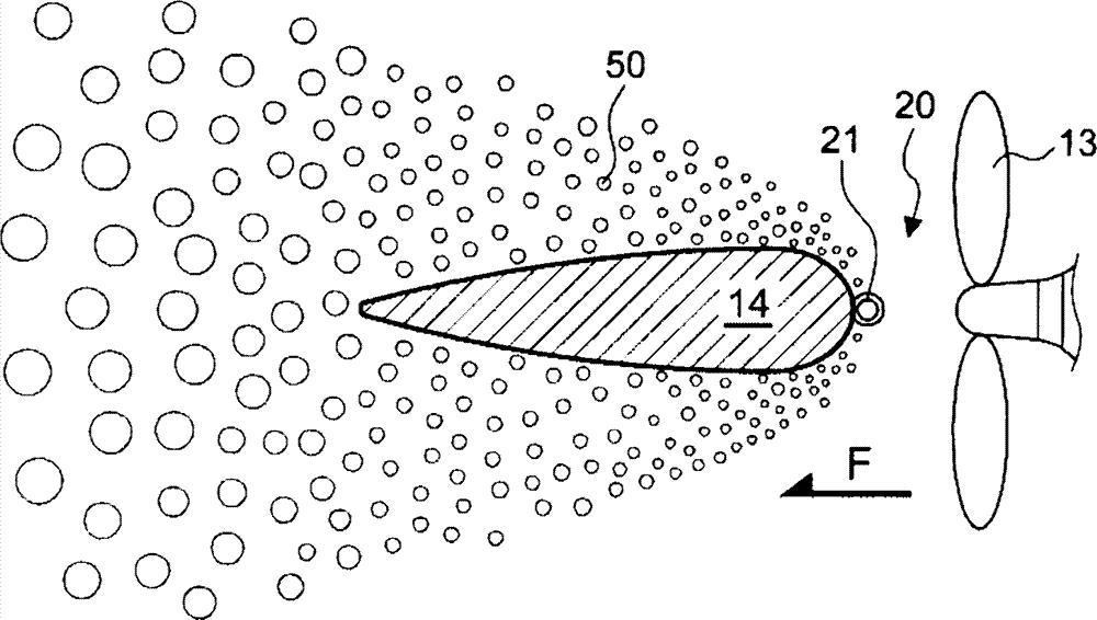
[0045] First, see Figure 3 ~ Figure 6 shown, where image 3 Shown is a schematic diagram that reveals that the gas bubbles 50 of the present invention reduce the resistance of the rudder, for use with figure 2 Existing ship rudder 14 surface resistance is compared; Figure 4 , Figure 5 Therefore, a preferred feasible embodiment of the present invention is disclosed, and its implementation steps and specific structure include:

[0046] a) A ship 10 is provided. In this embodiment, the hull 11 of the ship 10 has a propeller 13, which is driven by a power engine 131, so that the propeller 13 sends out a hig...


PUM


Abstract

The invention relates to a method for reducing rudder resistance of ships, in particular to a method for reducing underwater resistance of a rudder by means of leading in air bubbles in negative pressure. The method includes providing a ship with a screw propeller required for advancing of a hull and a rudder at the back of the screw propeller at preset positions; arranging an air bubble releaser at the front edge of the rudder; providing an air leading-in device which comprises at least one air guide pipe; utilizing high-speed water flow generated from the screw propeller during advancing of the hull to impact an upstream face of the rudder, and forming negative pressure at an air bubble releasing outlet according to the Bernoulli's principle to suck air; leading air into the air inlet through the air guide pipes, and releasing the air from the air bubble releasing outlet to mix with the water flow so as to form a great quantity of air bubbles. An air inlet is arranged at the upper end of each air guide pipe, and a lower section is connected to the air inlet of the air bubble releaser. By the method, high-speed water flow resistance generated from the rudder to the screw impeller can be reduced, and accordingly energy is saved.

Description

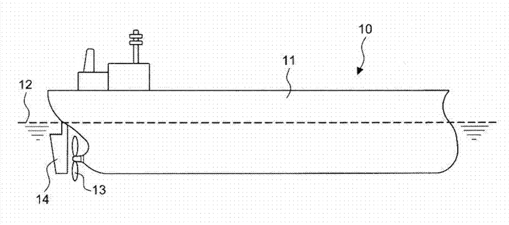
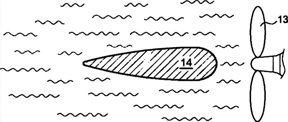
technical field [0001] The invention relates to a method for reducing the resistance of a ship's rudder, in particular to a method for reducing the resistance of a ship's rudder by utilizing negative pressure to introduce gas bubbles. Background technique [0002] In addition to the hull, there are pendants or hangers attached to the outside of the hull, such as: figure 1 The shown ship 10 includes a hull 11, and a propeller 13 pivotally arranged on the hull 11 and below the waterline 12, and the pendant behind the propeller 13 of the ship 10 shown in this figure is a ship rudder 14. to control the direction. [0003] figure 2 As shown, the water flow produced by the propeller 13 of the above-mentioned ship 10 flows through the schematic diagram of the rudder 14 of the ship. Since the rudder 14 of the ship is just at the downstream of the high-speed water flow of the propeller 13, the resistance of sailing will be increased, but the rudder 14 of the ship is this type. 10...

Claims


Application Information

Patent Timeline
Patent Type & Authority Applications(China)
IPC IPC(8): B63B1/38B63H25/38
CPCY02T70/122Y02T70/10
Inventor 林瑞麟
Owner 林瑞麟
Learn More