Load box for self-balanced method testing of concrete pipe pile

A technology of concrete pipe piles and load boxes, which is applied in the test of infrastructure, construction, infrastructure engineering, etc., can solve the problems of difficult load boxes, high costs, and many processes, and achieves reduction in design height, saving steel, and ensuring The effect of a solid connection

Inactive Publication Date: 2013-03-06
SOUTHEAST UNIV
View PDF4 Cites 13 Cited by
  • Summary
  • Abstract
  • Description
  • Claims
  • Application Information

AI Technical Summary

Problems solved by technology

This test method has many procedures and a long construction period. It is necessary to make a special joint according to the diameter of the pile. The production time of this joint is long and the cost is high. In addition, it may be difficult to connect the load box to the special joint during the test, which makes the test impossible.
At the same time, the recovered load box is difficult to put into the next test due to corrosion and other problems, which greatly reduces its economic benefits

Method used


Image

  • Load box for self-balanced method testing of concrete pipe pile
  • Load box for self-balanced method testing of concrete pipe pile
  • Load box for self-balanced method testing of concrete pipe pile

Examples


Embodiment Construction

[0019] The present invention will be further specifically described below in conjunction with the embodiments and the accompanying drawings.

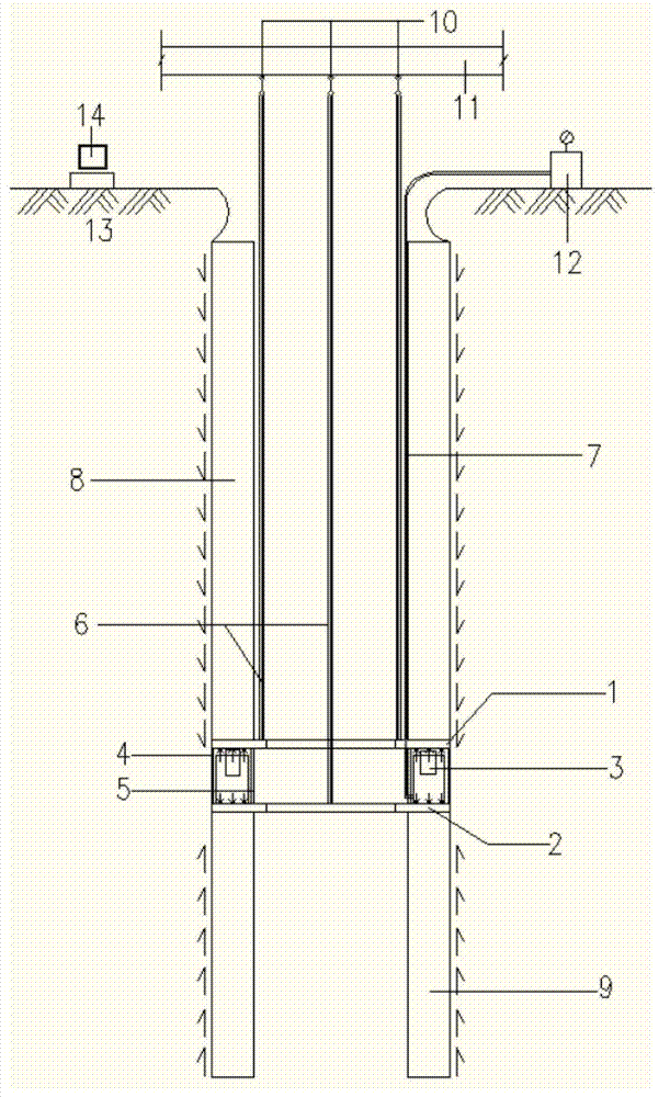
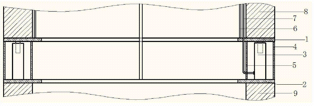
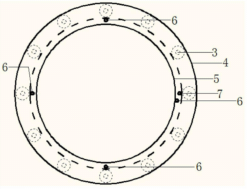
[0020] The load cell used for testing the self-balancing method of concrete pipe piles of the present invention includes an upper annular steel plate 1 and a lower annular steel plate 2 arranged symmetrically up and down, a hydraulic cylinder 3 arranged between the upper annular steel plate 1 and the lower annular steel plate 2, an outer The ring baffle 4 and the inner ring baffle 5, the number of hydraulic cylinders 3 is at least four, and the ring center of the upper annular steel plate 1 and the lower annular steel plate 2 is symmetrically distributed, and the bottom of the hydraulic cylinder 3 is connected by bolts. On the upper surface of the lower annular steel plate 2, the piston of the hydraulic cylinder 3 is connected to the bottom surface of the upper annular steel plate 1, the outer ring baffle 4 is located at the outer edge o...


PUM


Abstract

The invention discloses a load box for self-balanced method testing of a concrete pipe pile. The load box comprises an upper annular steel plate, a lower annular steel plate, hydraulic oil cylinders, an outer ring baffle plate and an inner ring baffle plate, wherein the upper annular steel plate and the lower annular steel plate are arranged symmetrically one above the other; the hydraulic oil cylinders are arranged between the upper annular steel plate and the lower annular steel plate; at least four the quantity of the hydraulic oil cylinders is at least four; the hydraulic oil cylinders are distributed symmetrically by taking the ring centers of the upper annular steel plate and the lower annular steel plate as the ring centers; the bottoms of the cylinder bodies of the hydraulic oil cylinders are connected to and arranged on the upper surface of the lower annular steel plate by adopting bolts; pistons of the hydraulic oil cylinders are connected with the bottom surface of the upper annular steel plate; the outer ring baffle plate is positioned on the outer edges of the upper annular steel plate and the lower annular steel plate; the upper end of the outer ring baffle plate is connected with the lower side of the upper annular steel plate by spot welding, and the lower end of the outer ring baffle plate is completely welded with the upper side of the lower annular steel plate; the inner ring baffle plate is positioned on the inner edges of the upper annular steel plate and the lower annular steel plate which are close to the hydraulic oil cylinders, and is kept consistent with the inner diameter of the pipe pile; and the upper end of the inner ring baffle plate is connected with the lower side of the upper annular steel plate by spot welding, and the lower end of the inner ring baffle plate is completely welded with the upper side of the lower annular steel plate.

Description

technical field [0001] The invention belongs to the technical field of pile foundation testing, and relates to a load box used for the self-balancing test of concrete pipe piles. Background technique [0002] The main device of the self-balancing pile measuring method for ordinary concrete piles is a specially designed load box for loading. The steel sleeve is solid, and an oil cylinder and a jack are provided near the wall pipe in the diameter direction of the pile. After the load box and the steel cage are welded into one body and put into the pile body, the concrete is poured and rammed to form a pile. During the test, the oil pump is used to pressurize the ground. As the pressure increases, the load box will be displaced upward and downward at the same time, which will promote the exertion of pile side resistance and pile end resistance. [0003] Concrete pipe pile self-balancing method is a test method developed for the special form of pipe piles. With the unique wide ...

Claims


Application Information

Patent Timeline
Patent Type & Authority Applications(China)
IPC IPC(8): E02D33/00
Inventor 龚维明戴国亮薛国亚杨超
Owner SOUTHEAST UNIV
Why Eureka
Try Eureka