
Downhole supercharging device

A pressurization device and casing technology, which is applied in the direction of flushing wellbore, wellbore/well components, earthwork drilling and production, etc. It can solve the problems of high cost, difficult manufacturing, complex supercharger structure, etc., and improve the service life , Reduce drilling cost and improve drilling efficiency

Inactive Publication Date: 2013-03-06
CNPC BOHAI EQUIP MFG
View PDF8 Cites 0 Cited by
  • Summary
  • Abstract
  • Description
  • Claims
  • Application Information

AI Technical Summary

Problems solved by technology

[0004] In order to overcome the disadvantages of complex structure, difficult manufacture and high cost of existing superchargers used in oil drilling operations, the present invention provides a downhole supercharging device

Method used


Image

  • Downhole supercharging device

Examples


Embodiment Construction

[0009] The present invention will be further described below in conjunction with drawings and embodiments. However, those skilled in the art should know that the present invention is not limited to the specific embodiments listed, as long as it conforms to the spirit of the present invention, it should be included in the protection scope of the present invention.

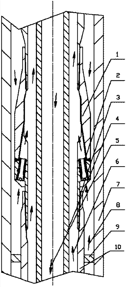
[0010] The downhole pressurization device of the present invention includes a casing 7, a pressurization string 10, and a drill string 4, which are installed sequentially from the outside to the inside. There is a ring between the inner hole of the booster string 10 and the outer circle of the drill string 4 The space between the outer circle of the pressurized string 10 and the inner hole of the casing 7 is an annulus.

[0011] The upper and lower ends of the cavity 1 of the booster string 10 are fixedly connected with a booster sleeve 3, and the booster sleeve 3 below the cavity 1 is equipped with a packer 9 for s...


PUM


Abstract

The invention discloses a downhole supercharging device, aiming to overcome defects that existing superchargers used in petroleum drilling operation are complicated in structure, high in manufacturing difficulty, high in cost and the like. The downhole supercharging device is characterized in that a supercharging string (10) is arranged between a casing (7) and a driller string (4), an annulus is reserved between an inner bore of the supercharging string (10) and the outer circle of the driller string (4), and another annulus is reserved between the outer circle of the supercharging string (10) and an inner bore of the casing (7). A supercharging casing (3), a cavity (1) and another supercharging casing (3) of the supercharging string (10) are sequentially fixedly connected from top to bottom, a packer mounted on the supercharging casing (3) below the cavity (1) is used for packing the annulus between the supercharging string (10) and the casing (7), and the annulus inside the cavity (1) and the annulus outside the cavity (1) are communicated by a supercharging water hole fixedly mounted on the cavity (1). The downhole supercharging device has the advantages of simple and reasonable structure and capability of increasing circulation speed of downhole liquid and improving rock breaking and sand carrying capacity on the premise of not changing rated pressure of a ground pumping pressure system.

Description

technical field [0001] The invention relates to a device for increasing the downhole circulating sand carrying speed in oil and gas drilling operations, in particular to a downhole pressurization device for oil drilling. Background technique [0002] In order to increase the drilling speed of oil and gas production, the research on the drilling fluid circulation system has been strengthened. Tests in the United States in the 1970s showed that when drilling with a circulation system with a high pump pressure of 105MPa on the ground, the ROP can be increased by 5 to 8 times. However, due to the limitation of high-pressure jet drilling system equipment, the application range is narrow. high cost. At present, the drilling fluid circulation system for drilling is used in special well conditions such as highly deviated wells and horizontal wells, and the ability to break rocks and carry sand is reduced, thereby affecting drilling efficiency. For example: when the pump pressure i...

Claims


Application Information

Patent Timeline
Patent Type & Authority Applications(China)
IPC IPC(8): E21B21/00
CPCE21B21/00E21B21/103E21B21/12
Inventor 于连杰张松峰魏向辉汪恩宝张林武强孙辉郭俊磊王晓彦
Owner CNPC BOHAI EQUIP MFG
Learn More