Double-cage rotor magnetic pump

A magnetic pump and rotor technology, applied in the field of double-cage rotor magnetic pumps, can solve the problems that cannot meet the requirements of different loads, it is difficult to realize the sinusoidal air gap magnetic field drive, and the starting and working performance cannot be satisfied, so as to reduce the starting time and reduce the Effect of Small Harmonic Loss

Inactive Publication Date: 2013-03-06
SHANGHAI DIANJI UNIV
View PDF5 Cites 1 Cited by
  • Summary
  • Abstract
  • Description
  • Claims
  • Application Information

AI Technical Summary

Problems solved by technology

The radial magnetization and parallel magnetization magnetic pumps currently used are difficult to achieve sinusoidal air gap magnetic field drive
In addition

Method used


Image

  • Double-cage rotor magnetic pump
  • Double-cage rotor magnetic pump
  • Double-cage rotor magnetic pump

Examples


Embodiment Construction

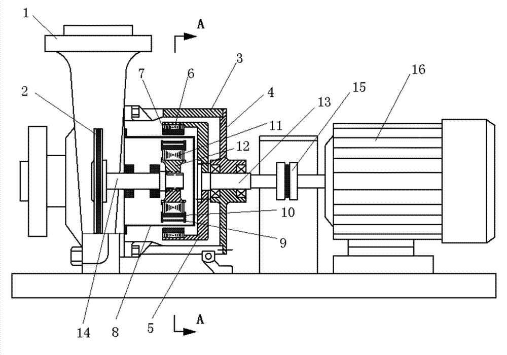
[0030] The specific implementation of the double-cage rotor magnetic drive pump of the present invention will be described in detail below in conjunction with the accompanying drawings.

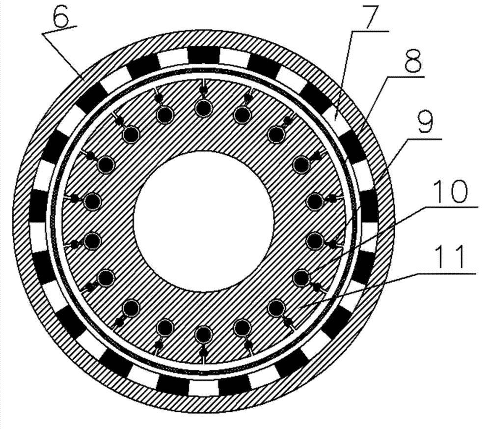
[0031] See attached figure 1 , 2 , 3. The double-cage rotor magnetic pump includes pump body 1 and casing 3. The casing 3 is installed on one side of the pump body 1, and a bearing seat is provided on one side of the casing 3, and the input is set through the bearing in the bearing seat. Shaft 13, in order to facilitate processing, one side of the housing 3 is an encapsulated end cover 4, the bearing seat is arranged on the end cover 4, the first end of the input shaft 13 is located inside the housing 3, and the second end of the input shaft 13 is in the It is connected to the rotating shaft of the motor 16 through a coupling 15 . The output shaft 14 is installed on the pump body 1 through bearing rotation, the first end of the output shaft 14 extends into the casing 3, the second end of th...


PUM


Abstract

The invention relates to the technical field of electromagnetic power, and provides a double-cage rotor magnetic pump, which comprises a motor, a pump body, a shell, an input shaft and an output shaft, wherein the input shaft is rotatably arranged at one side of the shell, and the first end of the input shaft is arranged in the shell; the second end of the input shaft is arranged outside the shell, and the output shaft is rotatably arranged on the pump body; the first end of the output shaft is arranged in the shell, and the second end of the output shaft is arranged in the pump body; a cup-shaped sleeve is arranged on the first end of the input shaft, and an annular outer magnetic rotor core is arranged on the inner side edge of the cup-shaped sleeve; an annular shaft sleeve is arranged at the first end of the output shaft, and an annular inner rotor core is arranged outside the annular shaft sleeve; an outer magnetic rotor magnet ring is arranged on the inner wall of the annular outer magnetic rotor core, and upper and lower mouse cages are arranged on the annular inner rotor core; and the inner rotor core and the upper and lower mouse cages form an inner rotor, and an annular gap is formed between the outer magnetic rotor magnet ring and the inner rotor. With the technical scheme provided by the invention, the air-gap magnetic flux density forms a sine waveform, and the harmonic loss of the core is reduced.

Description

technical field [0001] The invention relates to the technical field of electromagnetic power, in particular to a double-cage rotor magnetic pump. Background technique [0002] The magnetic pump is a kind of pump in which the outer magnetic rotor and the inner rotor cooperate to drive the inner rotor to rotate through magnetic force, and the inner rotor drives the pump shaft to rotate, so that the impeller rotor on the pump shaft in the pump body rotates to work. Generally, the inner and outer magnetic rotors are excited by permanent magnets, and have the same number of pole pairs, and the speed driven by the motor is the same as the speed of the impeller. The magnetic pump is compact in structure, beautiful in appearance, small in size, low in noise, and reliable in operation. Pumping of flammable and explosive liquids. [0003] In order to prevent demagnetization of the inner rotor, the inner rotor is generally designed using the operating principle of an induction motor....

Claims


Application Information

Patent Timeline
IPC IPC(8): F04D13/02F04D29/04F04D29/00H02K51/00
Inventor 杜世勤宋国强
Owner SHANGHAI DIANJI UNIV
Why Eureka
Try Eureka