Polarizing element unit, transmittance setting method of polarizing element unit, light irradiation apparatus using same

A technology of a light irradiation device and a polarizing element, which is applied to polarizing elements, optical elements, diffraction gratings, etc., can solve the problems of poor transmittance and uneven illuminance distribution in the light irradiation area, and achieve the effect of uniform illuminance distribution.

Inactive Publication Date: 2013-03-06
USHIO DENKI KK
View PDF8 Cites 5 Cited by
  • Summary
  • Abstract
  • Description
  • Claims
  • Application Information

AI Technical Summary

Problems solved by technology

However, if the transmittance of each polarizing element differs by a few percentage points, even if light of uniform illuminance enters the entire polarizing element unit, the illuminance distribution of the light irradiation area made by the light passing through the polarizing element is not uniform.

Method used


Image

  • Polarizing element unit, transmittance setting method of polarizing element unit, light irradiation apparatus using same
  • Polarizing element unit, transmittance setting method of polarizing element unit, light irradiation apparatus using same
  • Polarizing element unit, transmittance setting method of polarizing element unit, light irradiation apparatus using same

Examples


Embodiment Construction

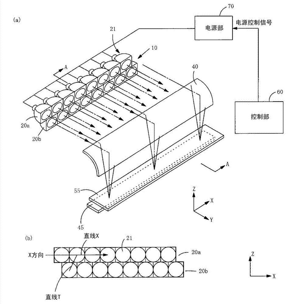
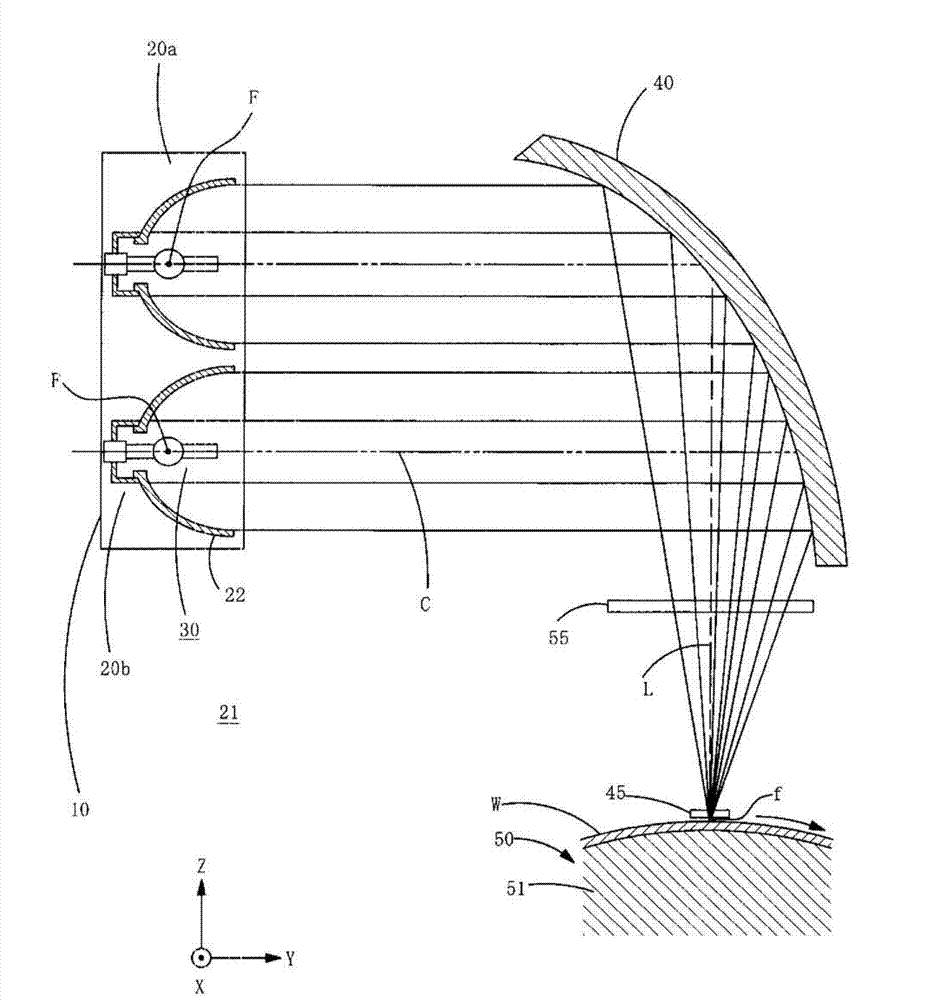
[0062] figure 1 is a diagram showing the overall schematic configuration of the light irradiation device according to the first embodiment of the present invention, figure 2 Yes figure 1 A-A cross-sectional view of the light irradiation device shown in (a). figure 1 (a) shows the overall schematic configuration of the light irradiation device, and FIG. 1(b) shows a view of the light emitting portion viewed from the light emitting side.

[0063] like figure 1 As shown in (a), the light irradiation device includes: a light emitting part 10; a reflecting mirror 40 that reflects the light from the light emitting part 10 and condenses the light into a line; and a polarizing element unit that polarizes the light reflected by the reflecting mirror 40 55; a mask 45 for shaping the polarized light from the polarizing element unit 55 into a striped shape; a power supply unit 70 for supplying electric power to the lamps of the light emitting unit 10; control unit 60 .

[0064] On t...


PUM


Abstract

A polarizing element unit, a transmittance setting method of polarizing element unit, and a light irradiation apparatus using the same, in the arrangement of multiple wire grid polarization components of polarization components unit, even if the polarization components of transmittance is individual difference, also make the light area of uniform illumination distribution. Multiple wire grid polarization element to the end in the direction of the light from the light source through overlapping way along the direction of array configuration in a box body, on the box body, and various polarization components corresponding to the set have to through the polarization components of light shading shading institutions. Shading institutions consists of multiple mask, the mask to the polarization components on the outstanding amount is variable, by changing the screen of the outstanding amount, to adjust the transmission the polarization components of light transmission. Thus, even if the wire grid polarization components of transmittance is individual difference, also can make each polarization components of the same amount of light transmission, can make the light area of uniform illumination distribution.

Description

technical field [0001] The present invention relates to a polarizing element unit in which a plurality of polarizing elements are arranged, and an alignment film for producing a liquid crystal display element using the polarizing element unit, and photo-alignment or 3D alignment of an alignment layer using a viewing angle compensation film of ultraviolet curable liquid crystal. A light irradiation device for a retardation film used in an image display device, and a method for setting the transmittance in which the transmittance of the polarizing element unit is set so as to be constant as a whole. Background technique [0002] For the alignment treatment of alignment films of liquid crystal display elements such as liquid crystal panels and alignment layers of retardation films (hereinafter referred to as films for 3D) used in 3D image display devices that display 3D images, polarization in the ultraviolet region that irradiates the alignment films is gradually adopted. The ...

Claims


Application Information

Patent Timeline
Patent Type & Authority Applications(China)
IPC IPC(8): G02B5/30G02B5/18
CPCG02B5/3058G02B27/286G02B30/25G02F1/13363G02F1/1337
Inventor 木尾智彦益田秀之
Owner USHIO DENKI KK
Why Eureka
Try Eureka