
Salient pole type alternating current synchronous generator rotor bobbin

A technology for synchronous generators and rotor wires, applied in synchronous generators, electrical components, electromechanical devices, etc., can solve the problems of poor ventilation and heat dissipation at the end of the coil, short service life, and high temperature of the motor, so as to save materials and reduce Cost, the effect of reducing the temperature rise of the motor

Active Publication Date: 2013-03-06
FUJIAN EVERSTRONG LEGA POWER EQUIP CO LTD
View PDF4 Cites 3 Cited by
  • Summary
  • Abstract
  • Description
  • Claims
  • Application Information

AI Technical Summary

Problems solved by technology

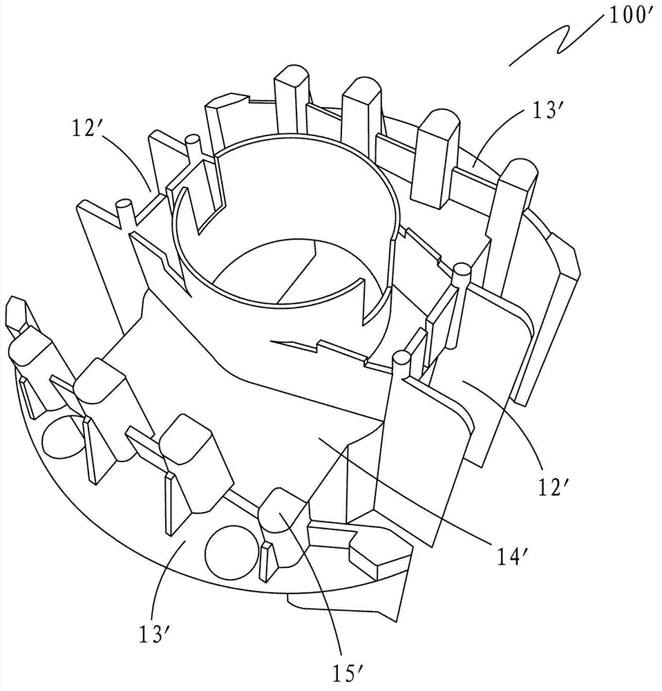
Existing salient-pole type AC synchronous generator rotor frame 100' such as figure 1 As shown, 5 to 8 square columns 15' are arranged at the outer side of each pole coil (not shown) on the outer surface 14' of the wire frame, and the entire row of columns 15' is placed between the outer walls of the coil slots 12' on both sides. Connect them to form a wall-like structure, so that the end, side and bottom of the coil are closely attached to the wire frame 100'. The purpose is to prevent the end of the coil from being thrown out under the action of centrifugal force when the rotor is running at high speed; in addition, the existing The outer periphery of the two magnetic pole sections 13' of the rotor wire frame 100' is arc-shaped, which conforms to the shape of the pole arc of the rotor core. The wire frame with this structure has the following disadvantages:
[0003] 1. Poor ventilation and heat dissipation at the end of the coil, resulting in high temperature of the motor, low efficiency and short service life;
[0004] 2. When the polarity of the magnetic steel is wrongly installed or the magnetic steel is damaged, it is not easy to replace;
[0005] 3. Complex structure, high material consumption and high cost

Method used


Image

  • Salient pole type alternating current synchronous generator rotor bobbin
  • Salient pole type alternating current synchronous generator rotor bobbin
  • Salient pole type alternating current synchronous generator rotor bobbin

Examples


Embodiment Construction

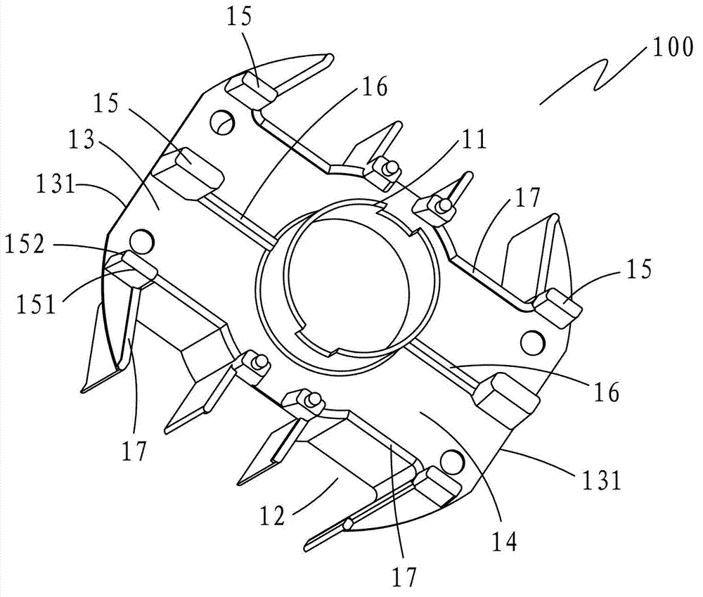
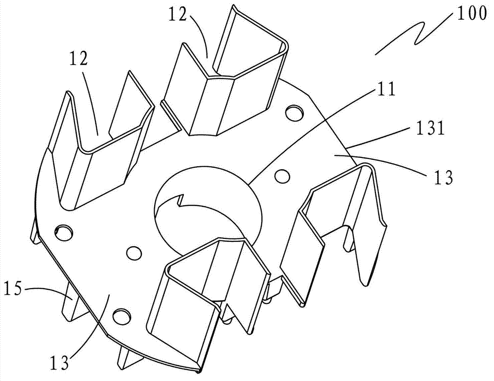
[0021] see Figure 2-3 , a salient pole AC synchronous generator rotor frame 100, including a frame body 1, the frame body 1 includes a shaft sleeve 11, four coil slots 12 and two pole segments 13; the outer body of the frame body 1 Six blades 15 are erected in parallel on the side 14, and the six blades 15 are arranged on the two magnetic pole segments 13 in pairs; the cross section of each blade 15 has a long side 151 and a short side 152, and the The short side 152 is arranged towards the outer periphery of the magnetic pole segment 13, so that the radial surface of the blade 15 is wider, but the outer contact surface between the blade 15 and the end of the coil (not shown) is smaller. This structure creates six The radial strength of the blade 15 is high, which can prevent the end of the coil from being thrown out under the centrifugal force, and at the same time, the outer surface of the coil is basically exposed to the air for heat dissipation. The function improves the...


PUM


Abstract

The invention provides a salient pole type alternating current synchronous generator rotor bobbin, which comprises a bobbin body, wherein the bobbin body comprises a shaft sleeve, four coil slots and two magnetic pole sections; the outer side face of the bobbin body is vertically provided with six blades in parallel; the six blades are arranged on the two magnetic pole sections with two blades opposite to each other; the cross section of each blade is provided with a long edge and a short edge; and the shot edge is arranged towards the periphery of the magnetic pole sections. The salient pole type alternating current synchronous generator rotor bobbin has the advantages of simple structure, attractive appearance, high strength, less used material, excellent ventilation and heat dissipation effects, low motor temperature rise, convenience in magnetic steel mounting or replacement and the like.

Description

【Technical field】 [0001] The invention relates to a generator rotor, in particular to a salient pole type AC synchronous generator rotor wire frame. 【Background technique】 [0002] The small salient-pole type 2-pole AC synchronous generator rotor frame is an integral, temperature-resistant, reinforced compression-plastic part. Existing salient pole type AC synchronous generator rotor frame 100' as figure 1 As shown, 5 to 8 square columns 15' are arranged at the outer side of each pole coil (not shown) on the outer surface 14' of the wire frame, and between the entire row of columns 15', and the outer walls of the coil slots 12' on both sides Connect them to form a wall-like structure, so that the end, side and bottom of the coil are closely attached to the wire frame 100'. The purpose is to prevent the end of the coil from being thrown out under the action of centrifugal force when the rotor is running at high speed; in addition, the existing The outer periphery of the two...

Claims


Application Information

Patent Timeline
Patent Type & Authority Applications(China)
IPC IPC(8): H02K19/16H02K3/46
Inventor 林朝文彭勇
Owner FUJIAN EVERSTRONG LEGA POWER EQUIP CO LTD
Learn More