Liquefied gas carrying ship

A technology for transport ships and liquefied gas, applied in the field of natural gas (LNG) LNG ships, can solve the problems of increased pressure area, increased wind pressure resistance, and increased position of the center of gravity of the ship, so as to reduce the pressure area and reduce the Wind pressure resistance, the effect of lowering the center of gravity

Active Publication Date: 2013-03-06
MITSUBISHI SHIPBUILDING CO LTD
View PDF7 Cites 12 Cited by
  • Summary
  • Abstract
  • Description
  • Claims
  • Application Information

AI Technical Summary

Problems solved by technology

[0006] However, in a (true) spherical vessel, since the cross-section of the hull of the LNG ship is approximately rectangular, the ratio of the volume inside the vessel to the volume of the compartment inside the vessel on which the spherical vessel is carried while being supported by the skirt is small, resulting in poor volumetric efficiency.
Therefore, the container cannot be completely accommodated in the hull, resulting in an increase in the size of the hull.
In addition, since the container and the container cover protrude high above the deck, the appearance viewed from the bridge is poor, and a high superstructure is required accordingly.
Therefore, there are problems that the pressure-receiving area of ​​the entire hull increases, and the wind pressure resistance increases, and the position of the center of gravity of the ship increases, and the stability deteriorates.

Method used


Image

  • Liquefied gas carrying ship
  • Liquefied gas carrying ship
  • Liquefied gas carrying ship

Examples


Embodiment Construction

[0045] Below, refer to Figure 1 to Figure 5 One embodiment of the liquefied gas carrier of the present invention will be described.

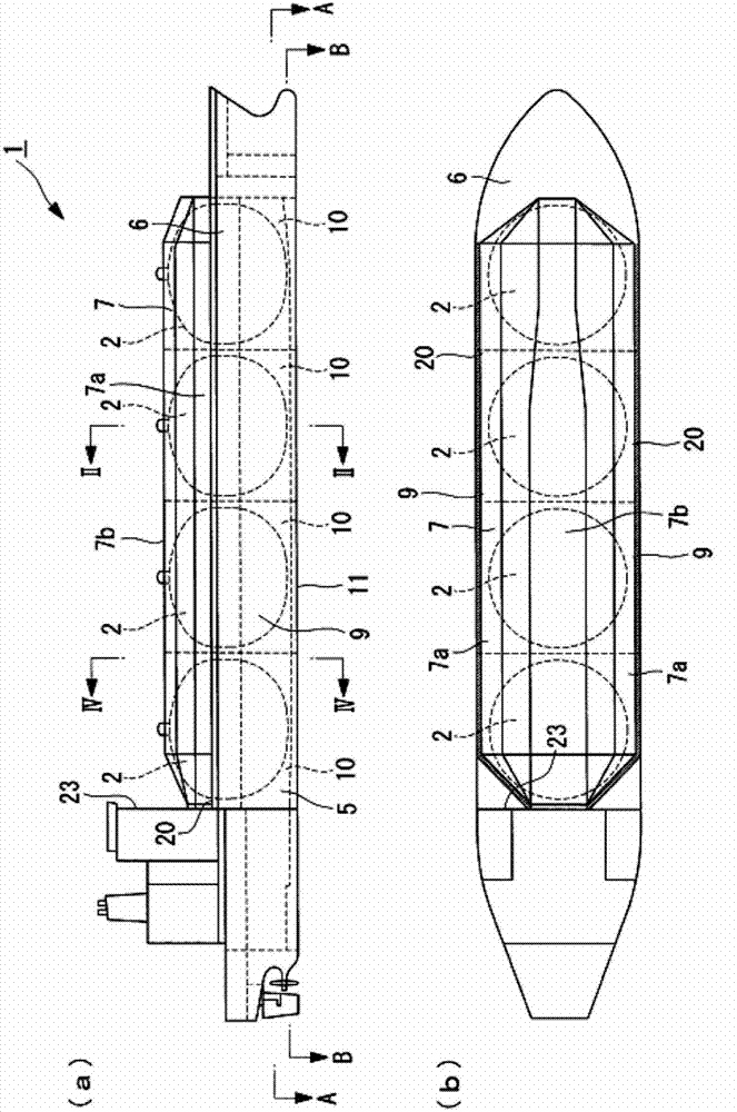
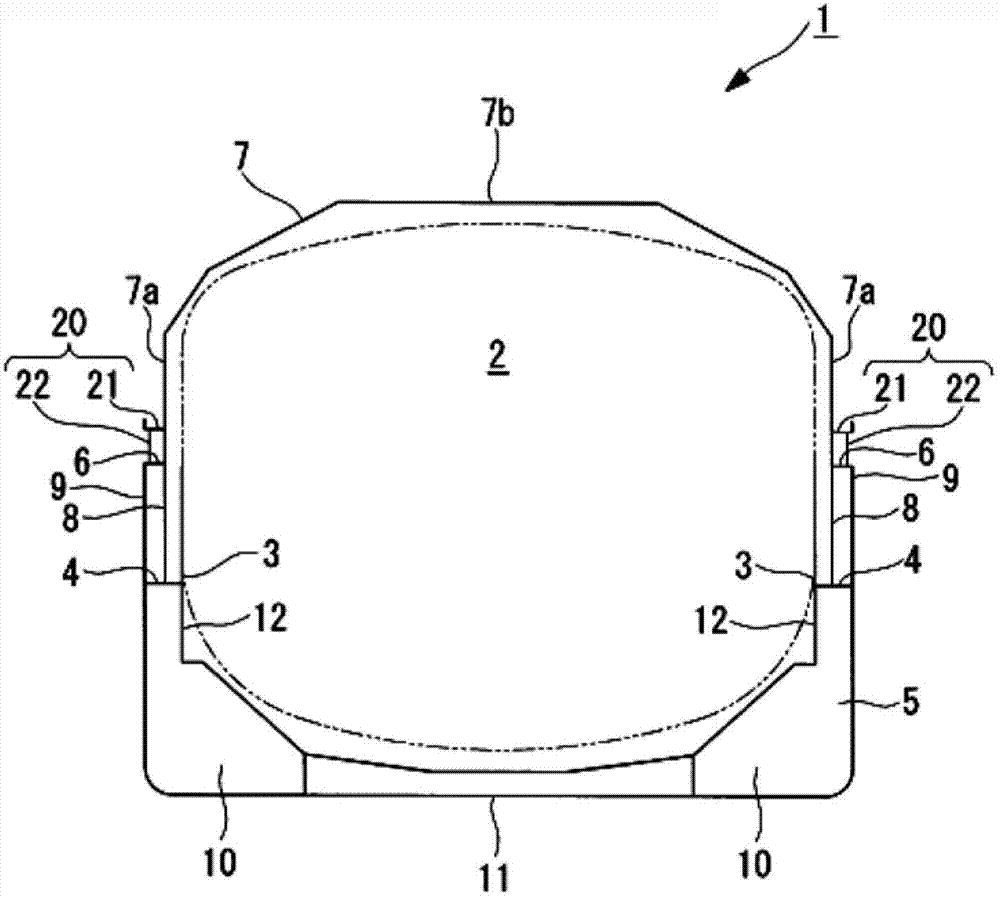
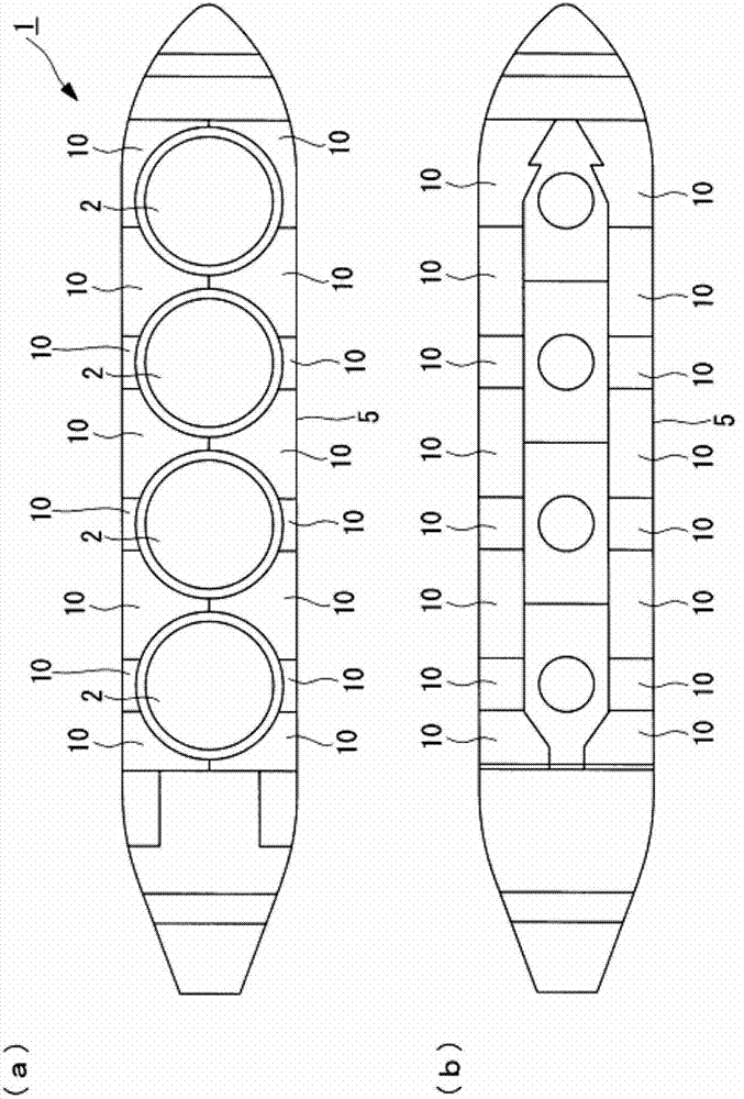
[0046] figure 1 It is a figure of the liquefied gas carrier ship of this embodiment, (a) is a right side view, (b) is a plan view, figure 2 yes figure 1 (a) II-II arrow sectional view, image 3 It is a figure of the liquefied gas carrier of this embodiment, (a) is figure 1 (a) A-A sectional view, (b) is figure 1 (b) The BB arrow section view, Figure 4 yes figure 1 (a) IV-IV section view, Figure 5 yes Figure 1 ~ Figure 3 (a) Side view of the flattened spherical vessel shown.

[0047] Such as figure 1 (a), figure 1 (b), and image 3 As shown in (a), the liquefied gas carrier ("LNG ship" in this embodiment) 1 of this embodiment is equipped with, for example, four flat spherical containers made of aluminum (also called "non-true spherical containers") 2 These aluminum-made flattened spherical containers 2 are configured so that liq...


PUM


Abstract

In order to reduce the pressure receiving area of the entire ship body, reduce the air pressure resistance, lower the position of the center of gravity of the ship, and improve the stability of the ship body, a liquefied gas carrying ship (1) is provided with: flat spherical tanks (2) for storing a liquefied gas therein, the flat spherical tanks (2) being arranged in the bow-stern direction of the ship and affixed to the ship body (5) through skirts (3); and a single continuous tank cover (7) for covering the upper half of the flat spherical tanks (2) and extending along the bow-stern and width directions of the ship. The tank cover (7) is rigidly joined to the ship body (5) and ensures, integrally with the ship body (5), the longitudinal strength.

Description

technical field [0001] The present invention relates to a liquefied gas carrier, in particular to an LNG carrier which stores and transports natural gas (LNG) liquefied at low temperature in a container. Background technique [0002] As a liquefied gas carrier that stores and transports natural gas (LNG) liquefied at low temperature in a container, there is known a liquefied gas carrier that covers a plurality of (true) spherical containers arranged in the fore and aft direction with one continuous container cover The upper half of (refer to Patent Document 1). [0003] prior art literature [0004] patent documents [0005] Patent Document 1: Japanese PCT Publication No. 2005-521589 [0006] However, in a (true) spherical vessel, since the cross-section of the hull of the LNG ship is approximately rectangular, the ratio of the volume inside the vessel to the volume of the compartment inside the vessel on which the spherical vessel is carried while being supported by the ...

Claims


Application Information

Patent Timeline
Patent Type & Authority Applications(China)
IPC IPC(8): B63B25/16B63B15/00B63B29/00B63B43/04
CPCB63B1/322B63B3/48Y02T70/12B63B25/16B63B2025/087Y02T70/10B63B15/00B63B29/00B63B43/04
Inventor 平松彩津村健司塚本泰史
Owner MITSUBISHI SHIPBUILDING CO LTD
Why Eureka
Try Eureka