Two-stage enthalpy increasing compressor

A compressor and enthalpy-increasing tube technology, applied in the field of compressors, can solve the problems of high development cost, complex processing, and difficulty in general use, and achieve the effects of reducing development and use costs, simplifying structure, and improving versatility

Active Publication Date: 2015-11-04
ZHUHAI GREE REFRIGERATION TECH CENT OF ENERGY SAVING & ENVIRONMENTAL PROTECTION
View PDF7 Cites 0 Cited by
  • Summary
  • Abstract
  • Description
  • Claims
  • Application Information

AI Technical Summary

Problems solved by technology

The pump body partition 11 and the lower cylinder 12 of the double-stage enthalpy-increasing compressor pump body parts are relatively similar to the double-cylinder pump body parts, and it is easy to change it from the pump body partition 21 and the lower cylinder 22 of the double-cylinder pump body, but the double-cylinder pump body The lower flange 13 of the pump body parts of the stage enthalpy-increasing compressor has been designed with a structure with an enthalpy-increasing cavity 14, which is different from the figure 2 Compared with the lower flange 23 of the double-cylinder pump body part shown in , the processing is complicated and it is difficult to be universal
Moreover, the pump body parts of the double-stage enthalpy-increasing compressor changed the lower muffler 24 in the double-cylinder pump body parts to the lower flange cover plate 15, so that the lower exhaust system in the double-cylinder pump body parts could not be borrowed.
[0005] It can be seen that the pump body parts of the above-mentioned two-stage enthalpy-increasing compressor have a complex structure, and the common level with the pump body parts of the two-cylinder compressor is low, and the development cost is relatively high.

Method used


Image

  • Two-stage enthalpy increasing compressor
  • Two-stage enthalpy increasing compressor
  • Two-stage enthalpy increasing compressor

Examples


Embodiment Construction

[0021] The embodiments of the present invention will be described in detail below with reference to the accompanying drawings, but the present invention can be implemented in many different ways defined and covered by the claims.

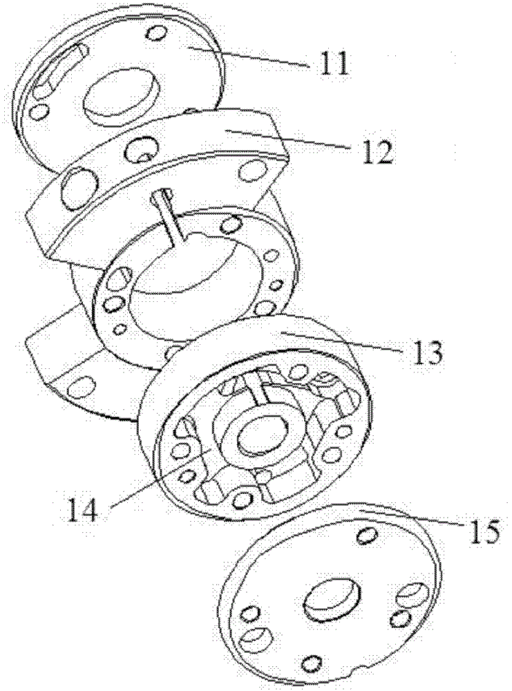
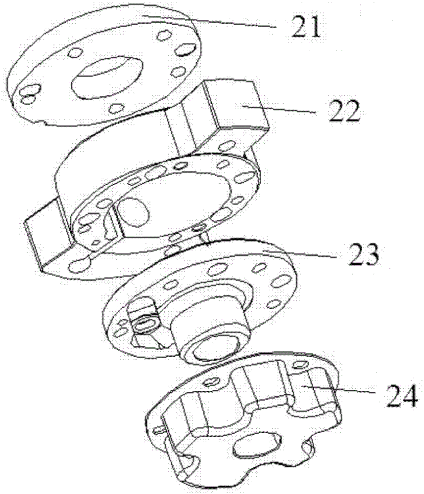
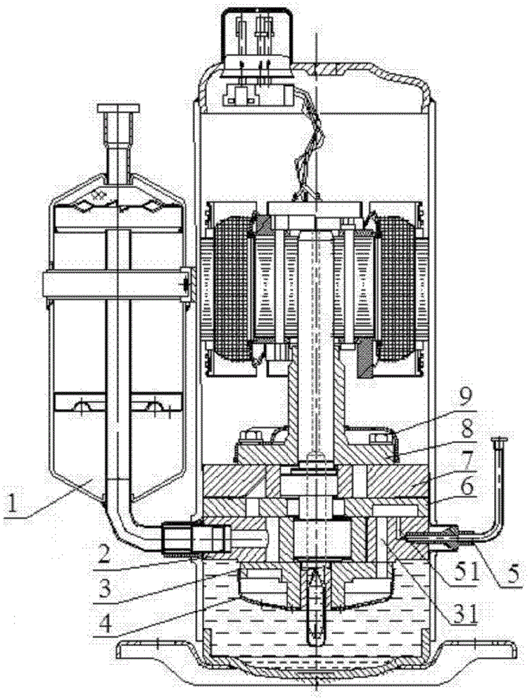
[0022] image 3 The schematic diagram of the side view of the two-stage enthalpy-increasing compressor of an embodiment of the present invention is shown in , comprising: a liquid separator assembly 1, a lower cylinder 2 (low-pressure cylinder), a lower flange 3, a lower muffler 4, and an enthalpy-increasing Pipe assembly 5, pump body partition 6, upper cylinder 7 (high pressure cylinder), upper flange 8, upper muffler 9. When the compressor is running, the refrigerant gas enters the lower cylinder 2 (low-pressure cylinder) from the liquid separator assembly 1 to be compressed, and the discharged high-temperature and medium-pressure refrigerant passes through the intermediate cavity between the lower flange 3 and the lower muffler 4, and then passes...


PUM


Abstract

The invention provides a two-stage enthalpy-increasing compressor which is orderly provided with: a pump body part comprising a low pressure cylinder, a pump body separation plate, and a high pressure cylinder; a liquid separator assembly with a lower end communicated with the low pressure cylinder; an enthalpy-increasing chamber; and an enthalpy-increasing pipe assembly communicated with the enthalpy-increasing chamber; wherein the enthalpy-increasing chamber is disposed on the pump body separation plate. According to the invention, the enthalpy-increasing chamber is disposed on the pump body separation plate, which simplifies the structure, and improves the generality with double cylinder compressor parts.

Description

technical field [0001] The invention relates to the field of compressors, in particular to a two-stage enthalpy increasing compressor. Background technique [0002] The existing compressor double-stage enthalpy increasing technology mainly provides enthalpy increasing holes on the low pressure cylinder or the lower flange, and the lower flange is designed as a structure with an enthalpy increasing cavity, and is sealed with the lower flange cover plate, and the enthalpy increasing gas The gas flowing through the enthalpy-increasing hole to the lower flange enthalpy-increasing chamber is mixed with the gas discharged from the low-pressure cylinder, and then enters the high-pressure cylinder through the flow channel for compression. [0003] figure 1 A schematic diagram of the parts structure of a two-stage enthalpy-increasing compressor pump body in the prior art is shown in . The figure shows that an enthalpy-increasing chamber 14 is provided in the lower flange 13, and th...

Claims


Application Information

Patent Timeline
Patent Type & Authority Patents(China)
IPC IPC(8): F04C23/00
Inventor 卢林高郑晓峰
Owner ZHUHAI GREE REFRIGERATION TECH CENT OF ENERGY SAVING & ENVIRONMENTAL PROTECTION
Why Eureka
Try Eureka