Magnetic-bias currency detecting magnetic head with sensitive direction parallel to detection face

A technology of magnetic bias and detection surface, which is applied in the authenticity inspection of banknotes, magnetic resonance measurement, and measurement devices, etc., and can solve the problems of low sensitivity and signal-to-noise ratio of indium antimonide Hall elements, sensitivity and signal-to-noise ratio of banknote verification heads Low ratio, large noise of indium antimonide sensor, etc., to achieve the effect of not being prone to environmental temperature and stress, low cost, high sensitivity and signal-to-noise ratio

Active Publication Date: 2013-03-13
MULTIDIMENSION TECH CO LTD
View PDF5 Cites 46 Cited by
  • Summary
  • Abstract
  • Description
  • Claims
  • Application Information

AI Technical Summary

Problems solved by technology

[0004] (1) The sensitivity and signal-to-noise ratio of the indium antimonide Hall element are very low, resulting in very low sensitivity and signal-to-noise ratio of this kind of banknote detection magnetic head;
[0005] (2) The indium antimonide sensor is significantly affected by temperature and requires a complex temperature compensation circuit;
[0006] (3) The inherent noise of the indium antimonide sensor is relatively large, so the magnetic bias element is required to provide a large bias signal to improve the signal-to-noise ratio, which leads to a large volume of the magnetic bias element, which in turn leads to the volume of the banknote verification head larger;
Due to the existence of this magnetic field component, it is difficult to accurately measure the magnitude of the magnetic field generated by the measured object

Method used


Image

  • Magnetic-bias currency detecting magnetic head with sensitive direction parallel to detection face
  • Magnetic-bias currency detecting magnetic head with sensitive direction parallel to detection face
  • Magnetic-bias currency detecting magnetic head with sensitive direction parallel to detection face

Examples


example 1

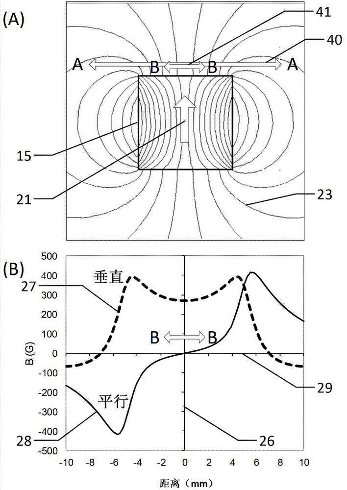
[0068] Figure 6 (A) is a magnetic field line distribution diagram of a magnetic field generated by a rectangular permanent magnet having a concave structure in the magnetic head according to Example 1 of the present invention. Such as Figure 6 As shown in (A), the permanent magnet 55 has a groove 52 on the surface close to the detection surface 40 , and the depth direction of the groove is perpendicular to the surface of the permanent magnet 55 formed with the groove. The magnetization direction 51 of the permanent magnet 55 is perpendicular to the detection surface 40 . At the center of the detection surface 40, the magnetic field 53 generated by the permanent magnet 55 with the groove 52 is perpendicular to the detection surface 40, thus eliminating the horizontal magnetic field component at the sensor chip 41 such as the TMR element.

[0069] Figure 6 (B) is a magnetic field intensity distribution diagram along the detection surface 40, wherein the dotted line 57 is t...

example 2

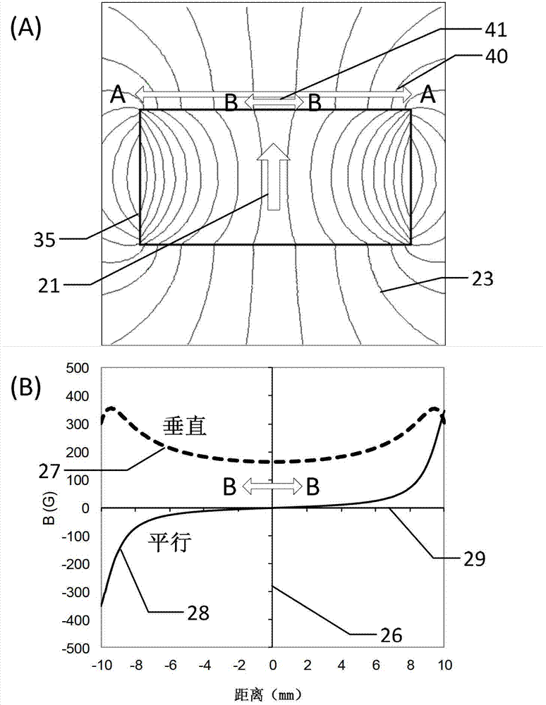
[0072] Figure 7 (A) is a distribution diagram of the magnetic force lines of the magnetic field generated by the magnetic bias element in the magnetic head of Example 2. Such as Figure 7 (A), the permanent magnet with a rectangular cross-section 65 is covered with a soft magnetic alloy sheet, also called “magnetic pole piece” 64 , which is used to adjust the magnetic field distribution parallel to the detection surface 40 . Pole pieces 64 are typically made of a soft magnetic alloy, such as permalloy. The magnetization direction 61 of the permanent magnet 65 is perpendicular to the detection surface 40 , and the magnetization direction of the pole piece 64 is determined by the magnetization direction of the permanent magnet 65 . The groove 62 of the pole piece is used to reduce the magnetic field strength of the magnetic field in the direction parallel to the detection surface 40 .

[0073] Figure 7 (B) is the magnetic field intensity distribution diagram of example 2 alo...

example 3

[0076] Figure 8 (A) is a distribution diagram of the magnetic force lines of the magnetic field generated by the magnetic bias element in the magnetic head of Example 3. Such as Figure 8 As shown in (A), the permanent magnet with a rectangular cross section 75 is covered with a soft magnetic alloy sheet, also called a magnetic pole piece 74 , which is used to adjust the magnetic field distribution of the permanent magnet parallel to the detection surface 40 . Pole pieces 74 are typically made of a soft magnetic alloy, such as permalloy. The magnetization direction 71 of the permanent magnet 75 is perpendicular to the detection surface 40 , and the magnetization direction of the pole piece 74 is determined by the magnetization direction of the permanent magnet 75 . The opening 72 on the pole piece 74 is used to reduce the strength of the magnetic field parallel to the detection surface 40 .

[0077] Figure 8 (B) is a magnetic field intensity distribution diagram along th...


PUM


Abstract

The invention relates to a magnetic-bias currency detecting magnetic head with sensitive direction parallel to a detection face. The currency detecting magnetic head comprises a magnetoresistive sensor chip and a magnetic-bias unit, wherein the magnetic-bias unit and the magnetoresistive sensor chip are separately placed on one side of the magnetoresistive sensor chip away from the detection face of the currency detecting magnetic head. The magnetoresistive sensor chip comprises a bridge circuit provided with a magnetic sensitive element on a bridge arm, the sensitive direction of the magnetic sensitive element is parallel to the detection face of the currency detecting magnetic head, and the magnetic-bias unit is provided with a sunken structure which is set to enable a component of a magnetic field produced by the magnetic-bias unit to be small so as to enable the magnetic sensitive element to work in a linear region. The magnetic-bias currency detecting magnetic head has high sensitivity and signal to noise ratio.

Description

technical field [0001] The invention relates to the technical field of magnetoresistive sensors, in particular to a magnetoresistance banknote detection magnetic head. Background technique [0002] In daily life, banknote detection magnetic heads are widely used, such as vending machines, banknote counters, and banknote inspection equipment. Generally, the magnetic properties of banknotes are very weak, therefore, the banknote verification magnetic head used to identify the magnetic properties of banknotes needs to have the characteristics of high sensitivity, low noise and high signal-to-noise ratio. [0003] figure 1 It shows a banknote verification magnetic head in the prior art, the sensor element in the banknote verification magnetic head detects the magnetic field component perpendicular to the detection surface of the magnetic head, and the magnetic field is generated by the magnetic ink on the banknote. Typically, the material used for this sensor element is indium...

Claims


Application Information

Patent Timeline
Patent Type & Authority Applications(China)
IPC IPC(8): G07D7/04
CPCG01R33/09G07D7/04G01N27/90G01R15/20G01R33/0283G01R33/091G01R33/38G11C19/085
Inventor 詹姆斯·G·迪克刘明峰白建民诸敏
Owner MULTIDIMENSION TECH CO LTD
Why Eureka
Try Eureka