
Design method for passive bipyramid test antenna

A technology for testing antennas and design methods, which is applied in the direction of the structure connection of the antenna grounding switch and the structural form of the radiating element, can solve the problems of the large size, influence, and inconvenience of the antenna, and achieves a small size, no tuning, and easy disassembly and portability. Effect

Inactive Publication Date: 2013-03-13
XIAN KAIRONG ELECTRONICS TECH
View PDF5 Cites 1 Cited by
  • Summary
  • Abstract
  • Description
  • Claims
  • Application Information

AI Technical Summary

Problems solved by technology

However, due to the large size of these antennas, they are not easy to carry, and the frequent replacement and disassembly of the antenna structure will have a certain impact on the test results.

Method used


Image

  • Design method for passive bipyramid test antenna
  • Design method for passive bipyramid test antenna

Examples


Embodiment Construction

[0015] The invention is a miniaturized portable broadband passive double-cone test antenna, which can test 50MHz-3.2GHz radiation emission.

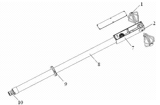
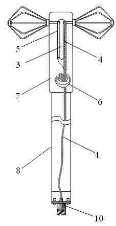
[0016] see figure 1 and figure 2 , the concrete structure of the design method of a kind of passive biconical test antenna of the present invention is:

[0017] Including two small conical antenna oscillators 1, threaded inner conductor 2, impedance transformation device 3, radio frequency coaxial cable 4, half steel rod 5, magnetic ring 6, antenna box body 7, antenna pole 8, limit ring 9 and RF connector 10; wherein, two small conical antenna vibrators 1 are symmetrically distributed on both sides of the impedance transformation device 3, and pass through the threaded inner conductor 2 at the end and the thread of the impedance transformation device 3 built in the antenna box 7 respectively. The hole is connected, and the impedance transformation device 3 is composed of a radio frequency coaxial cable 4, a magnetic ring 6 and a half ...


PUM


Abstract

The invention relates to a design method for a passive bipyramid test antenna. The passive bipyramid test antenna comprises two small cone-shaped antenna oscillators, a thread inner conductor, an impedance conversion device, a radio frequency coaxial cable, a semisteel rod, a magnet ring, an antenna box body, an antenna supporting rod, a limiting ring and a radio frequency connector, wherein the two small cone-shaped antenna oscillators are symmetrically distributed on two sides of the impedance conversion device and are respectively connected with a threaded hole of the impedance conversion device arranged in the antenna box body through the thread inner conductor positioned at the end. The impedance conversion device is composed of the radio frequency coaxial cable, the magnet ring and the semisteel rod. The antenna box body is connected with the top end of the antenna supporting rod, the radio frequency coaxial cable penetrates through the antenna supporting rod and is welded to the radio frequency connector arranged at the tail of the antenna supporting rod, and the limiting ring is sleeved on the antenna supporting rod. The passive bipyramid test antenna can not only be used for measurement of electromagnetic field radiation emission, but also be used for measurement of radiosensitivity or noise immunity, and has the advantages of not needing tuning and being convenient to dismantle and carry and small in size and the like.

Description

technical field [0001] The invention relates to a test antenna for a calibration test and an electromagnetic compatibility radiation interference test system, in particular to a design method for a passive biconical test antenna. The invention belongs to the technical field of electronic testing and radiation emission testing. Background technique [0002] In order to meet the needs of the development of modern electronic technology, the research and development of antennas are mainly developed in the direction of small size and wide frequency band. In the field of electromagnetic compatibility, passive large biconical antennas and horn antennas are often used to receive electric field interference leaked from the device under test and environmental electromagnetic field interference. However, due to the large size of these antennas, they are not easy to carry, and frequent replacement and disassembly of the antenna structure will have a certain impact on the test results...

Claims


Application Information

Patent Timeline
Patent Type & Authority Applications(China)
IPC IPC(8): H01Q1/36H01Q1/50
Inventor 曹盼盼宋博
Owner XIAN KAIRONG ELECTRONICS TECH
Learn More