Single-drive bidirectional disk-shaped linear piezoelectric motor

A piezoelectric motor and disk-shaped technology, which is applied in the direction of piezoelectric effect/electrostrictive or magnetostrictive motors, generators/motors, electrical components, etc., can solve small size, affect the focusing effect, and contain components Miniaturization and simplification, better miniaturization and simplification

Inactive Publication Date: 2013-03-13
NINGBO INST OF MATERIALS TECH & ENG CHINESE ACADEMY OF SCI
View PDF7 Cites 6 Cited by
  • Summary
  • Abstract
  • Description
  • Claims
  • Application Information

AI Technical Summary

Problems solved by technology

[0004] The piezoelectric drive mechanism used for lens drive includes screw drive type and direct drive type. The typical screw drive type is a micro piezoelectric motor-lens integrated drive mechanism disclosed in Chinese patent ZL200710022415.9, including ring Piezoelectric stator, rotor and drive power supply, wherein: the annular piezoelectric stator is provided with internal threads, the rotor is annular or cylindrical with external threads, and the rotor is integrated with the lens; the external threads of the rotor are connected with the The internal threads are matched; the rotor is screwed into the stator through mutually matched threads; its advantages are: a piezoelectric stator is provided with an ultra-thin ring structure, and the lens is directly driven as a part of the rotor, which has relatively higher driving force and efficiency , the screw drive also has the characteristics of insensitivity to vibration; since the piezoelectric element on the piezoelectric stator is a sheet-like or multi-layer sheet structure, the motor can be allowed to work at a lower voltage; s

Method used


Image

  • Single-drive bidirectional disk-shaped linear piezoelectric motor
  • Single-drive bidirectional disk-shaped linear piezoelectric motor
  • Single-drive bidirectional disk-shaped linear piezoelectric motor

Examples


Example Embodiment

[0042] Example 1

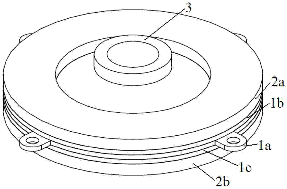
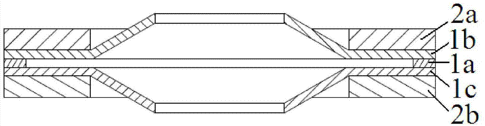
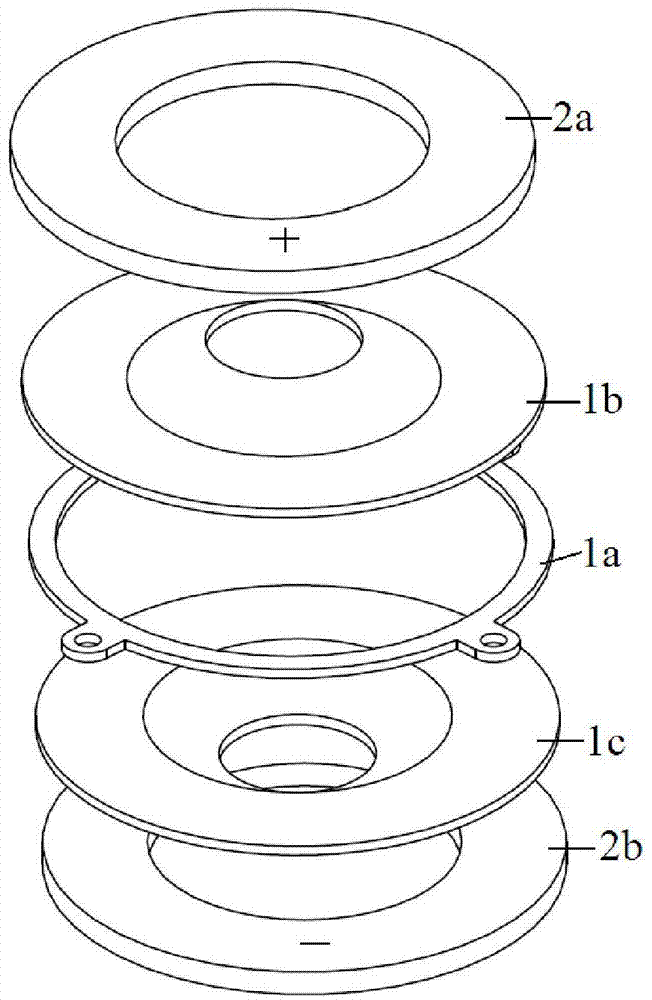
[0043] Such as figure 1 , figure 2 , image 3 with Figure 4 As shown, the single-drive bidirectional disc-shaped linear piezoelectric motor of the present invention includes a stator and a mover 3 slidable relative to the stator. The stator is composed of a vibrating body and two circular piezoelectric ceramic sheets 2a and a circular piezoelectric The vibrating body is composed of a circular ring-shaped fixed bracket 1a and two identical pot-shaped ring pieces 1b and a pot-shaped ring piece 1c. The pot-shaped ring piece 1b is provided with a protrusion 4a, and the center of the protrusion 4a is provided Through hole, the bowl-shaped ring piece 1c is provided with a protrusion 4b, and the central part of the protrusion 4b is provided with a through hole. The protrusion 4a and the protrusion 4b are in opposite directions; the two bowl-shaped ring pieces 1b and the bowl-shaped ring piece 1c are symmetrically pasted On both sides of the fixed bracket 1a and matc...

Example Embodiment

[0045] Example 2

[0046] Such as Figure 5 , Image 6 , Figure 7 with Figure 8 As shown, the single-drive bidirectional disc-shaped linear piezoelectric motor of the present invention includes a stator and a mover 3 that can slide relative to the stator. The stator is composed of a vibrating body and 8 arc-shaped piezoelectric ceramic sheets 2a. 2b, arc piezoelectric ceramic sheet 2c, arc piezoelectric ceramic sheet 2d, arc piezoelectric ceramic sheet 2e, arc piezoelectric ceramic sheet 2f, arc piezoelectric ceramic sheet 2g, arc piezoelectric ceramic sheet 2h , The vibrating body is composed of a ring-shaped fixed bracket 1a, two identical pot-shaped ring pieces 1b, and a pot-shaped ring piece 1c. The protruding directions of the pot-shaped protrusions of the two pot-shaped ring pieces are opposite. The central part of the shaped protrusion is provided with a through hole; the protrusion part and most of the ring of the bowl-shaped ring piece 1b are divided into equal ring se...

Example Embodiment

[0048] Example 3

[0049] Such as Picture 9 , Picture 10 , Picture 11 with Picture 12 As shown, the single-drive bidirectional disc-shaped linear piezoelectric motor of the present invention includes a stator and a mover 3 that can slide relative to the stator. The stator is composed of a vibrating body and 8 arc-shaped piezoelectric ceramic sheets 2a. 2b, arc-shaped piezoelectric ceramic sheet 2c, arc-shaped piezoelectric ceramic sheet 2d, arc-shaped piezoelectric ceramic sheet 2e, arc-shaped piezoelectric ceramic sheet 2f, arc-shaped piezoelectric ceramic sheet 2g, arc-shaped piezoelectric ceramic sheet 2h The main body of the vibrating body is an annular fixed bracket 1. The inner ring of the annular fixed bracket 1 is provided with four two-by-two arc-shaped protrusions 4a, arc-shaped protrusions 4b, arc-shaped protrusions 4c and a circle. For the arc-shaped protrusion 4d, the protrusion directions of the two opposite protrusions are the same, that is, the protrusion dire...


PUM


Abstract

The invention discloses a single-drive bidirectional disk-shaped linear piezoelectric motor, comprising a stator and a rotor, wherein the stator comprises a vibrator and at least two piezoelectric ceramic sheets symmetrically arranged at the both sides of the vibrator; the vibrator comprises a vibrator body and protruding parts in contact with the vibrator body and protruding relative to the vibrator body; a through hole is arranged on the protruding part; the through hole and the rotor are in interference fit; and the protruding directions of the two protruding parts are opposite. The piezoelectric motor uses a disk-shaped driving structure, and integrates a lens to be the rotor of the linear piezoelectric motor. Compared with a threaded driving type motor, the single-drive bidirectional disk-shaped linear piezoelectric motor has balance pre-stress, has no 'hula-hoop' motion and stable motion, and can realize a thinned design through a disk-shaped driving structure integrated with the lens. Furthermore, the bidirectional motion can be realized through one path of a driving signal circuit when the single-drive bidirectional disk-shaped linear piezoelectric motor is in use, and the microminiaturization and the simplification of the driving circuit can be realized better.

Description

technical field [0001] The invention relates to the field of micro-drive mechanisms, in particular to a single-drive bidirectional disc-shaped linear piezoelectric motor. Background technique [0002] Piezoelectric motors, as a precision piezoelectric drive element, are becoming key components in advanced technology products such as mobile phones, personal computers, medical imaging systems and other miniature medical devices. Compared with the traditional electromagnetic drive mechanism, the piezoelectric actuator has relatively high power density, large driving force and high driving step accuracy. [0003] At present, many researchers have devoted themselves to the development of miniature linear piezoelectric motors as precision drives, especially for miniature camera modules, but compared with the current rapid development of mobile phones, the micro Drive components are relatively lacking. Compared with traditional electromagnetic drive components (such as voice coil...

Claims


Application Information

Patent Timeline
IPC IPC(8): H02N2/02H02N2/04
Inventor 邢增平何彬徐凯
Owner NINGBO INST OF MATERIALS TECH & ENG CHINESE ACADEMY OF SCI
Why Eureka
Try Eureka