Conveyer device

A technology of conveying device and conveying wheel, applied in the field of conveying device, can solve the problems of inconvenient maintenance and replacement, unstable cable conveying, heavy weight of conveying device, etc., and achieve convenient replacement and maintenance, low manufacturing cost and light weight. Effect

Active Publication Date: 2013-03-20
NANTONG XUNXIANG AUTOMATION EQUIP
View PDF4 Cites 3 Cited by
  • Summary
  • Abstract
  • Description
  • Claims
  • Application Information

AI Technical Summary

Problems solved by technology

However, the conveying device of this structure is heavy in weight, and generally requires two workers to move, which is inconvenient to move; and its structure is more complicated, and the installation of the chain driving the sprocket rotation is more complicated, resulting in inconvenient maintenance and replacement; in addition, the two The rotation of a sprocket drives the delivery wheel, ...

Method used


Image

  • Conveyer device
  • Conveyer device
  • Conveyer device

Examples


Embodiment Construction

[0014] The present invention will be described in further detail below in conjunction with the accompanying drawings and specific embodiments.

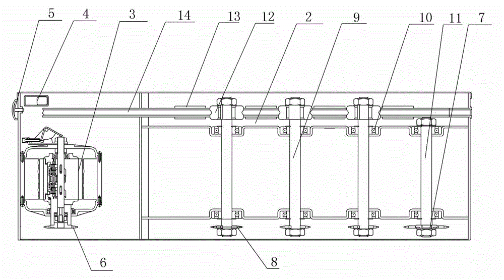
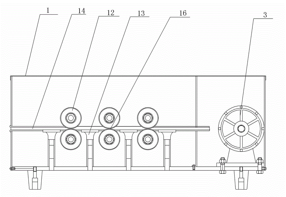
[0015] Such as figure 1 , figure 2 and image 3 shown;

[0016] The conveying device of the present invention comprises a housing 1, a bracket 2 is arranged in the housing 1, a motor 3 is arranged on the bracket 2, and a drive sprocket 6 is fixedly connected to the rotating shaft of the motor 3, so that Said bracket 2 is also provided with a transition sprocket 7, said transition sprocket 7 is connected with the drive sprocket 6 on the motor 3 rotating shaft through a chain 15 which is closed into a loop; the transition sprocket 7 and the drive sprocket 6 The support 2 between is provided with multiple sets of horizontally distributed delivery wheel mechanisms, each set of delivery wheel mechanisms includes two rotating shafts 9 arranged up and down and connected to the support 2 in rotation, and two belt V belts are installed at ...


PUM


Abstract

The invention discloses a conveyer device, and the conveyer device comprises a shell body, a support and an electrical machine. A rotating shaft of the electrical machine is fixedly connected with a driving sprocket. The support is further provided with a transitional sprocket, wherein the transitional sprocket is in driving connection with the drive sprocket arranged on the electrical machine through a chain which is closed to be annular. The support is provided with multiple sets of conveying wheel mechanisms which are arranged horizontally. Each of the conveying wheel mechanisms comprises two rotating shafts which are connected with the support in a rotating mode, wherein one of the two rotating shafts is arranged above the other rotating shaft. Two conveying wheels with V-shaped wheel troughs are arranged at one ends of the two rotating shafts. A conveying interspace is arranged between the two conveying wheels. The support is further provided with a conveying passage, wherein two ends of the conveying passage penetrate through the shell body. The conveying interspace between the two conveying wheels of each the set of conveying wheel mechanism is communicated with the conveying passage. Two driving sprockets are arranged at the one ends of the two rotating shafts. The bottom of the upper portion of the chain is meshed with the driving sprocket above each the set of the conveying wheel mechanisms. The bottom of the lower portion of the chain is meshed with the driving sprocket under each the set of the conveying wheel mechanisms.

Description

technical field [0001] The invention relates to a conveying device, in particular to a conveying device capable of conveying cables, network cables, electric wires and the like. Background technique [0002] At present, conveying devices are required to transport and lay cables, network cables and wires during room decoration and road line maintenance. The conveying device of the prior art, such as a patent called a cable conveyor disclosed on the website of the State Intellectual Property Office, includes a main frame and a conveying device composed of a motor, a speed change device, a transmission device and a conveying wheel. The left and right ends are each pivotally equipped with a V-shaped conveying wheel, and the motor drives the large sprocket on the left and right conveying wheel shaft through the main sprocket group on the transmission device; a pressure wheel is fixed on the main frame Frame, on this pinch wheel frame corresponding to directly above the two V-sha...

Claims


Application Information

Patent Timeline
IPC IPC(8): B65H51/08
Inventor 陆颂荫
Owner NANTONG XUNXIANG AUTOMATION EQUIP
Why Eureka
Try Eureka